Supercharge Your Innovation With Domain-Expert AI Agents!

Control device, communication relay device, communication system and communication control method

a control device and relay technology, applied in the field of controlling communication, can solve the problems of deteriorating the radio performance of the access point as a whole, affecting the efficiency of communication, so as to achieve efficient distribution

Active Publication Date: 2020-11-17
YAMAHA CORP
View PDF14 Cites 0 Cited by
  • Summary
  • Abstract
  • Description
  • Claims
  • Application Information

AI Technical Summary

Benefits of technology

Efficiently distributes communication terminals across multiple modules, improving radio performance and user convenience by balancing the number of connections and reducing processing times through controlled connection management.

Problems solved by technology

Such an imbalance in the number of connected communication terminals deteriorates the radio performance of the access point as a whole.
According to the technology disclosed in JP-A-2009-284487, since the load is distributed by complex processing and such processing is conducted after the authentication processing of the communication terminal, processing takes time as a whole, which deteriorates user convenience.

Method used


Image

  • Control device, communication relay device, communication system and communication control method
  • Control device, communication relay device, communication system and communication control method
  • Control device, communication relay device, communication system and communication control method

Examples


first embodiment

[1. Overview]

[0017]A communication system in a first embodiment of the present invention is implemented by an access point that relays radio communication. This access point is a communication relay device having a plurality of radio communication modules, and is capable of distributing the communication terminals connected to the communication modules by the method described below. The access point in the first embodiment will be described. The communication system may be implemented by a router instead of the access point.

[2. Structure of the Access Point]

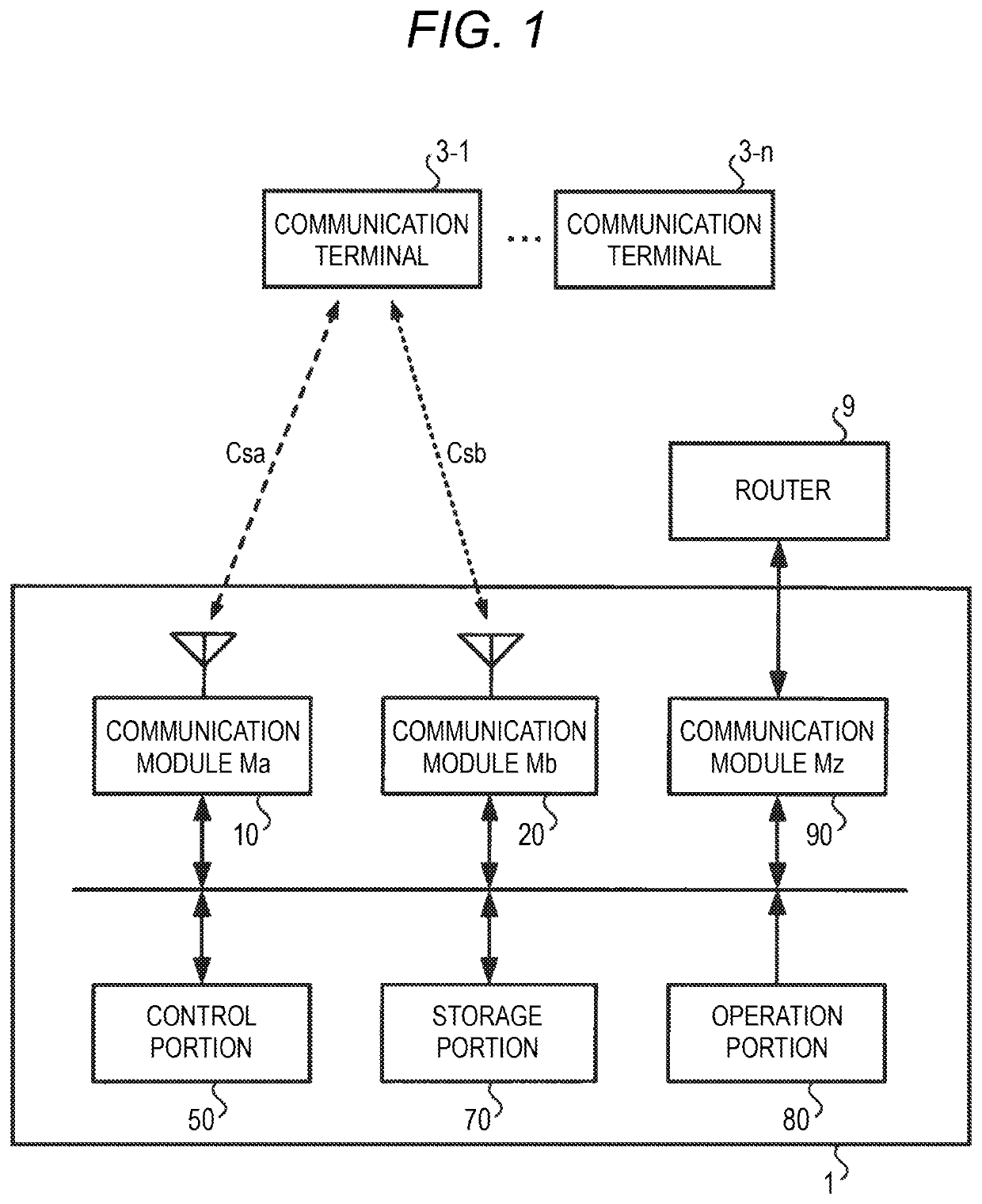
[0018]FIG. 1 is a view explaining the structure of a communication system in the first embodiment of the present invention. The access point 1 provides communication terminals 3-1, . . . , 3-n (hereinafter, referred to as communication terminal 3 when they are not specifically distinguished from one another) with a wireless LAN environment, and performs relay for connecting the communication terminal 3 to a WAN (the Internet, etc...

second embodiment

[0037]While in the first embodiment, the communication control processing using the MAC address filter of the white list form is used, in a second embodiment, communication control processing is used where whether to permit connection or not is controlled every time a connection request is received from the communication terminal 3.

[0038]FIG. 5 is a flowchart explaining the communication control processing in the second embodiment of the present invention. When the communication control processing is started, the control portion 50 waits for a request for connection to the communication modules Ma10 and Mb20 to be received from the communication terminal 3 (step S50; No). In the following description, this state will be referred to as request waiting state. When receiving a request for connection to the communication module Ma10 from the communication terminal 3 (step S50; received at Ma), the control portion 50 determines whether a history of connection of this communication termin...

third embodiment

[0046]While the communication module Ma10 and the communication module Mb20 are accommodated in the same housing (access point 1) in the first embodiment, in a third embodiment, they are accommodated in different housings (access points 1A and 1B).

[0047]FIG. 6 is a view explaining the structure of a communication system in the third embodiment of the present invention. As shown in FIG. 6, the access point 1A has a structure where the communication module Mb20 is removed from the access point 1 of the first embodiment. On the other hand, the access point 1B of another housing has the communication module Mb20. The access point 1A and the access point 1B are connected through the router 9 in this example. For this reason, the control portion 50 of the access point 1A transmits a control signal for controlling the communication module Mb20 to the access point 1B through the router 9. Thereby, when this control signal is received at the access point 1B, the communication module Mb20 is ...


PUM


Abstract

A control device includes a memory that stores instructions and a processor that executes the instructions. The instructions cause the processor to perform: controlling, based on a first number of communication terminals to which a first module performs radio communication and a second number of communication terminals to which a second module performs radio communication, whether to permit the communication terminal having made a request for connection to the first module to connect to the first module or not.

Description

CROSS REFERENCE TO RELATED APPLICATIONS[0001]This application is based on Japanese Patent Application (No. 2018-055088) filed on Mar. 22, 2018, the contents of which are incorporated herein by reference.BACKGROUND OF THE INVENTION1. Field of the Invention[0002]The present invention relates to a technology of controlling communication.2. Description of the Related Art[0003]By making the same connection restriction setting (security setting) at an access point having a plurality of radio communication modules, for example, a roaming technology is realized. Although communication terminals as clients can connect to any of the communication modules, there are cases where while many communication terminals are connected to one communication module, hardly any communication terminals are connected to the other communication modules. Such an imbalance in the number of connected communication terminals deteriorates the radio performance of the access point as a whole. Accordingly, a technol...

Claims


Application Information

Patent Timeline
Patent Type & Authority Patents(United States)
IPC IPC(8): H04W48/02H04W76/15H04W88/04
CPCH04W48/02H04W76/15H04W88/04H04W76/19
Inventor SUZUKI, HIROKAZU
Owner YAMAHA CORP
Features
  • R&D
  • Intellectual Property
  • Life Sciences
  • Materials
  • Tech Scout
  • Unparalleled Data Quality
  • Higher Quality Content
  • 60% Fewer Hallucinations
Learn More