Step attachment for ladders

Active Publication Date: 2020-11-24
LAN ALEX
View PDF46 Cites 2 Cited by
  • Summary
  • Abstract
  • Description
  • Claims
  • Application Information

AI Technical Summary

Benefits of technology

[0005]This invention assists the user with greater surface area to stand and perform work activities safely and comfortably. Some of the safety features designed into th

Problems solved by technology

Presently one of the major problems of being on an extension ladder or step ladder for a lengthy work session, such as painting, is the pain and discomfort one feels in the feet.
The reason for this pain is that the rungs

Method used


Image

  • Step attachment for ladders
  • Step attachment for ladders
  • Step attachment for ladders

Examples


Embodiment Construction

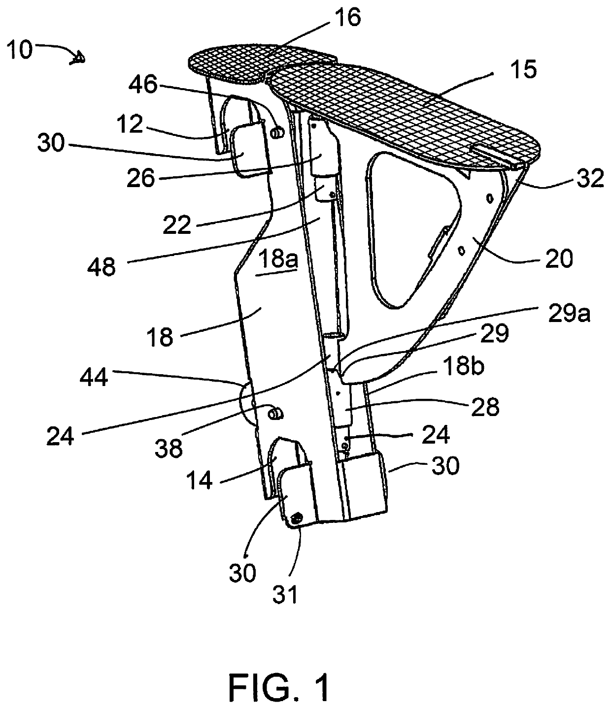
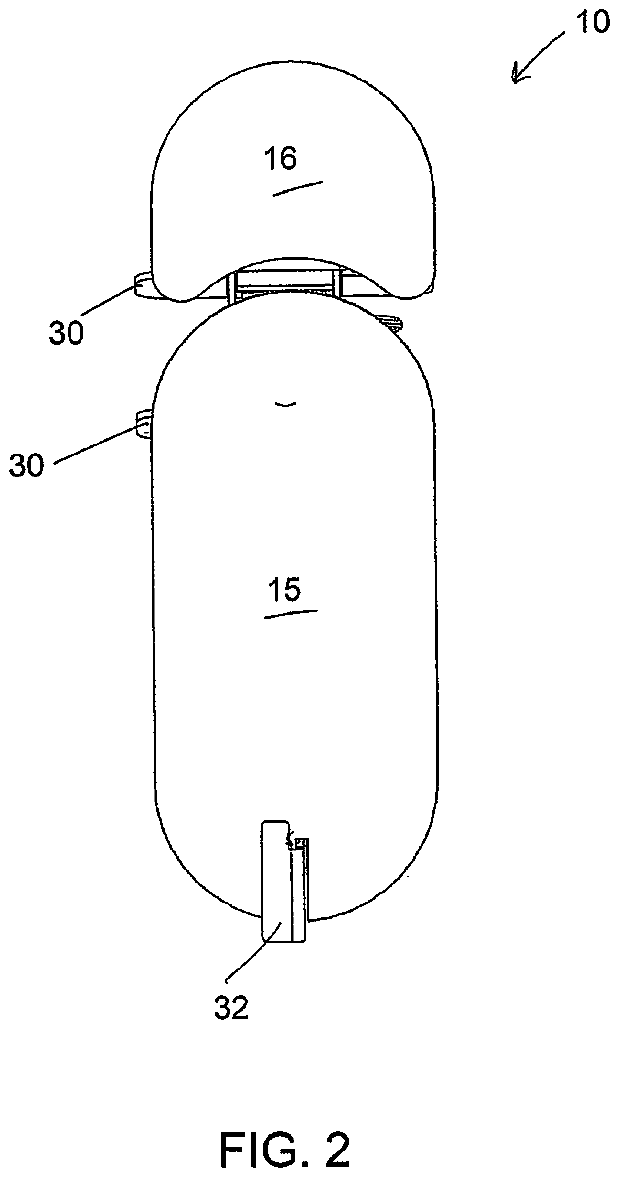
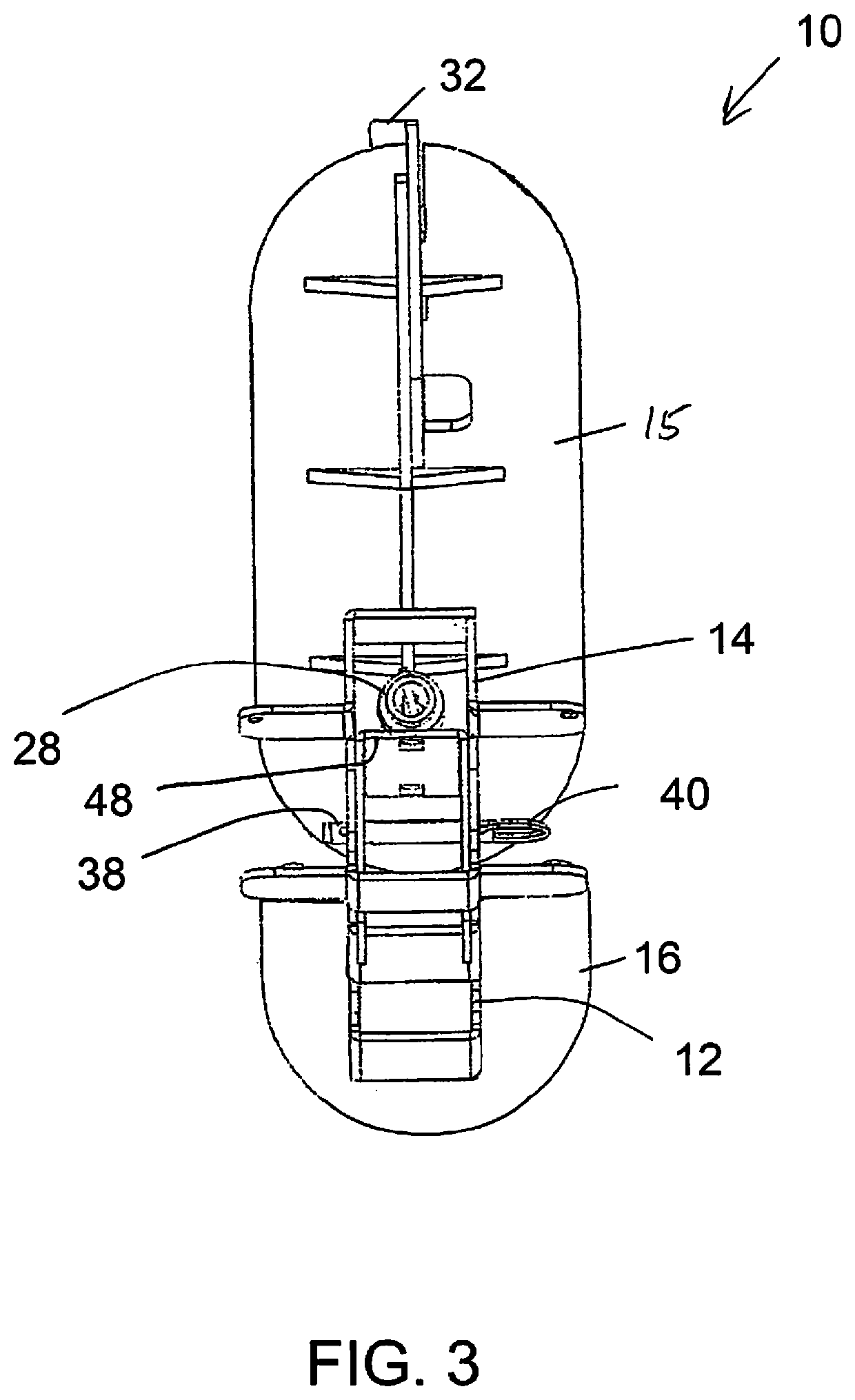
[0024]In the drawings, the ladder accessory of the invention is best understood with reference to FIG. 1, along with FIGS. 2 through 4. FIGS. 7A and 7B show the accessories in place on a ladder. The portable step platform device 10, preferably formed of metal such as steel or aluminum, includes upper and lower hooks 12 and 14 to engage over successive rungs of a ladder. These hooks are spaced apart to fit a standard ladder, normally about 12 inches from the center of one rung to the center of the next rung. The hooks are designed for essentially cylindrical rungs such as on an extension ladder or a similar rail-and-rung ladder in a single section. Some ladders vary somewhat in rung spacing, but almost all rung ladders have a rung spacing of 12 inches plus or minus ⅛ inch. The two hooks 12 and 14 have sufficient depth to accommodate a small range of variation, accommodating almost all rung type ladders.

[0025]A foot platform in a preferred embodiment is formed by a main foot platform ...


PUM


Abstract

A portable step platform fits onto the hollow rungs of an extension or step ladder, providing support, security and comfort for the user performing work related tasks on the ladder. A user can easily move the device up or down on the ladder, or swing the platform out of the way when ascending or descending. Tilt adjustment is facilitated for the foot platform, to accommodate different ladder inclinations. In addition, the portable step platform is configured to allow support of a scaffold plank on the top surface.

Description

[0001]This application claims benefit of provisional application No. 62 / 603,499, filed Jun. 1, 2017.BACKGROUND OF THE INVENTION[0002]This invention relates to portable steps or platforms that are adjustable, portable and mountable on a standard rung ladder. A foot pad platform is adapted to be used with generally vertically or steeply disposed ladders having side rails and a plurality of rungs.[0003]Presently one of the major problems of being on an extension ladder or step ladder for a lengthy work session, such as painting, is the pain and discomfort one feels in the feet. That pain in the trades is called rung foot.[0004]The reason for this pain is that the rungs or support decks designed for extension ladders and other ladders are much too small to carry the weight evenly and comfortably for a person performing work tasks for extended periods, sometimes through the day or night.SUMMARY OF THE INVENTION[0005]This invention assists the user with greater surface area to stand and p...

Claims


Application Information

Patent Timeline
IPC IPC(8): E06C7/16
CPCE06C7/165E06C7/18
Inventor HALLORAN, KEVIN JOHNHALLORAN, MICHAEL
Owner LAN ALEX
Why Eureka
Try Eureka