Straddle mount connector for a pluggable transceiver module

Active Publication Date: 2013-02-07
TYCO ELECTRONICS LOGISTICS AG (CH)
View PDF1 Cites 3 Cited by
  • Summary
  • Abstract
  • Description
  • Claims
  • Application Information

AI Technical Summary

Benefits of technology

[0004]In one embodiment, a straddle mount connector is provided for edge mounting to a circuit board of a pluggable module. The straddle mount connector includes a dielectric connector body having a base and a plug extending from the base. The base is configured to be coupled to an edge of the circuit board. The plug has opposite first and second sides and a plate cavity that extends within the plug between the first and second sides. The plug is configured to be received within a receptacle of a receptacle connector. Electrical contacts are held by the connector body. The electrical contacts include mating segments. The mating segments of a first group of the electrical contacts are arranged in a first row that extends a length along the first side of the plug. The mating segments of a second group of the electrical contacts are arranged in a second row that extends a length along the second side of the plug. A ground plate is held within the plate cavity of the plug of the connector body. The ground plate extends between the first and second rows of electrical contacts along the lengths of the first and second rows.
[0005]In another embodiment, a straddle mount connector is provided for edge mounting to a circuit board of

Problems solved by technology

However, because of the increased signal rates and/or higher density, differential pairs of signal contacts within a transceiver assembly may interfere with each other, which is commonly referred to as “crosstalk”.
Such crosstalk can become a relatively large contributor to errors along the signal paths of the transceiver assembly.
Coupling between signal contacts within the sa

Method used


Image

  • Straddle mount connector for a pluggable transceiver module
  • Straddle mount connector for a pluggable transceiver module
  • Straddle mount connector for a pluggable transceiver module

Examples


Example

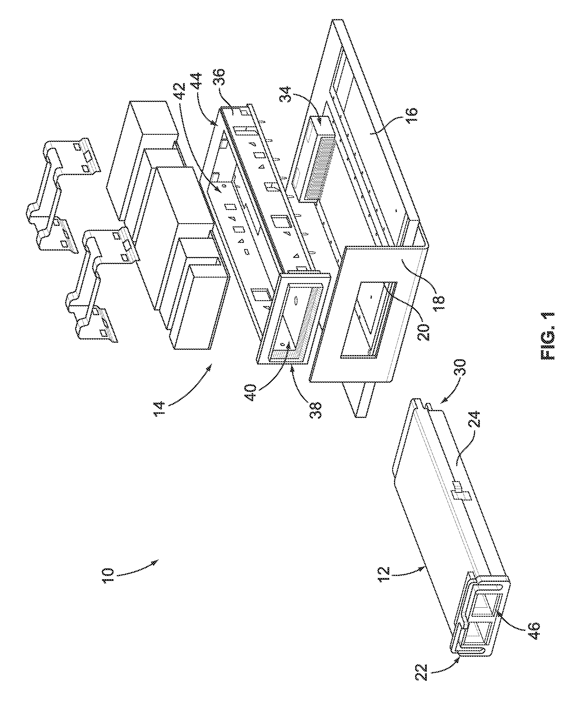
[0023]FIG. 1 is a perspective view of a portion of an exemplary embodiment of a transceiver assembly 10. In the exemplary embodiment, the transceiver assembly 10 is adapted to address, among other things, conveying data signals at high rates, such as data transmission rates of at least 10 gigabits per second (Gbps), which is required by the SFP+ standard. For example, in some embodiments the transceiver assembly 10 is adapted to convey data signals at a data transmission rate of at least 28 Gbps. Moreover, and for example, in some embodiments the transceiver assembly 10 is adapted to convey data signals at a data transmission rate of between approximately 20 Gbps and approximately 30 Gbps. It is appreciated, however, that the benefits and advantages of the subject matter described and / or illustrated herein may accrue equally to other data transmission rates and across a variety of systems and standards. In other words, the subject matter described and / or illustrated herein is not li...


PUM


Abstract

A straddle mount connector is provided for edge mounting to a circuit board of a pluggable module. The straddle mount connector includes a dielectric connector body having a base and a plug extending from the base. The base is configured to be coupled to an edge of the circuit board. The plug has opposite first and second sides and a plate cavity that extends within the plug between the first and second sides. The plug is configured to be received within a receptacle of a receptacle connector. Electrical contacts are held by the connector body. The electrical contacts include mating segments. The mating segments of a first group of the electrical contacts are arranged in a first row that extends a length along the first side of the plug. The mating segments of a second group of the electrical contacts are arranged in a second row that extends a length along the second side of the plug. A ground plate is held within the plate cavity of the plug of the connector body. The ground plate extends between the first and second rows of electrical contacts along the lengths of the first and second rows.

Description

BACKGROUND OF THE INVENTION[0001]The subject matter described and / or illustrated herein relates generally to transceiver assemblies.[0002]Various types of fiber optic and copper based transceiver assemblies that permit communication between host equipment and external devices are known. These transceiver assemblies typically include a module assembly that can be pluggably connected to a receptacle connector in the host equipment. The module assemblies are constructed according to various standards for size and compatibility, one standard being the Quad Small Form-factor Pluggable (QSFP) module standard. Conventional QSFP modules and receptacle assemblies perform satisfactorily conveying data signals at rates up to 10 gigabits per second (Gbps). Another pluggable module standard, the XFP standard, calls for the transceiver module to also convey data signals at rates up to 10 Gbps.[0003]As electrical and optical devices become smaller, the signal paths thereof become more densely grou...

Claims


Application Information

Patent Timeline
IPC IPC(8): H01R24/00
CPCH01R12/721H01R13/6461G02B6/4278G02B6/4246H01R13/6586
Inventor CINA, MICHAEL FRANKHENRY, RANDALL ROBERTPHILLIPS, MICHAEL J.SZCZESNY, DAVID
Owner TYCO ELECTRONICS LOGISTICS AG (CH)
Why Eureka
Try Eureka