Method of measuring adhesive strength

a technology of adhesive strength and measurement method, which is applied in the direction of instruments, mechanical devices, and mechanical devices using mechanical means, can solve the problems of wide achieve the effects of reducing the variation in the measured adhesive strength, suppressing the damage of the porous protection layer, and improving measurement accuracy

Active Publication Date: 2020-11-24
NGK INSULATORS LTD
View PDF5 Cites 2 Cited by
  • Summary
  • Abstract
  • Description
  • Claims
  • Application Information

AI Technical Summary

Benefits of technology

[0015]In the above case, the through hole of the peeling jig may have a size and shape with which a gap ratio defined as (a length of a gap between an inner circumferential surface of the through hole and the element body) / (a thickness of the porous protection layer) and derived in a direction perpendicular to the surface of the element body becomes 0.3 or greater and 0.7 or smaller in a state where the element body is set in the through hole in the step (a). If the gap ratio is 0.3 or greater, at least one of the following advantageous effects is obtained, for example: the element body can be easily inserted into the through hole of the peeling jig in the step (a), and the occurrence of an error in the adhesive strength that may be caused by the frictional force generated at the contact between the peeling jig and the element body in the step (b) can be suppressed. If the gap ratio is 0.7 or smaller, the porous protection layer can be more assuredly peeled off the element body by using the peeling jig.
[0016]Herein, the expression “the gap ratio derived in a direction perpendicular to the surface of the element body becomes 0.3 or greater and 0.7 or smaller” implies that, at a position on at least any of the surfaces of the element body, the gap ratio derived in a direction perpendicular to that surface is 0.3 or greater and 0.7 or smaller. Furthermore, at a position on any of the surfaces of the element body that are covered by the porous protection layer, the gap ratio derived in a direction perpendicular to that surface is preferably 0.3 or greater and 0.7 or smaller. That is, in the state where the element body is set in the through hole in the step (a), it is preferable that there be no area where the gap ratio is out of the range of 0.3 or greater and 0.7 or smaller.
[0017]In the method of measuring adhesive strength according to the present invention, the porous protection layer and the peeling jig may have respective preventing portions at respective positions that come into contact with each other in the step (b), the preventing portions preventing, when fitting each other, the porous protection layer and the peeling jig from moving in a predetermined direction perpendicular to the longitudinal direction. In such a case, since the preventing portion of the porous protection layer and the preventing portion of the peeling jig fit each other in the step (b) and thus prevent the porous protection layer and the peeling jig from moving in the predetermined direction perpendicular to the longitudinal direction, the displacement between the porous protection layer and the peeling jig in that direction that may occur in the step (b) is suppressed. Consequently, the variation in the measured adhesive strength can be made much smaller. In such a case, one of the preventing portion of the porous protection layer and the preventing portion of the peeling jig may be a projection, while the other may be a recess that fits the projection.
[0018]In the method of measuring adhesive strength according to the present invention, the holding jig may include an elastic member in a portion that comes into contact with the element body in the step (a), the elastic member having a hardness of 60 or greater and 1300 or smaller, the hardness being measured with a type-A durometer in accordance with JIS K 6253-3:2012. If the hardness of the elastic member is 60 or greater, the coming off of the element body from the holding jig that may occur in the step (b) can be suppressed. If the hardness of the elastic member is 1300 or smaller, the breakage of the element body that may occur under the holding force exerted by the holding jig can be suppressed.
[0019]In the method of measuring adhesive strength according to the present invention, a speed at which the holding jig and the peeling jig move away from each other in the step (b) may be set to 0.8 mm / sec or higher and 1.2 mm / sec or lower. If the speed is set to 0.8 mm / sec or higher, the occurrence of a phenomenon other than peeling, such as slight and gradual damage to the porous protection layer, can be suppressed. Consequently, measurement accuracy is improved. If the speed is set to 1.2 mm / sec or lower, at least one of the following advantageous effects is obtained: the error in the load measurement that may be caused by high speed can be reduced, and the coming off of the element body from the holding jig can be suppressed.
[0020]In the method of measuring adhesive strength according to the present invention, the porous protection layer may have a thickness of 40 μm or greater and 800 μm and smaller. If the porous protection layer has a thickness of 40 μm or greater, the peeling jig can easily push the porous protection layer in the longitudinal direction in the step (b). That is, the porous protection layer can be easily peeled off by using the peeling jig.

Problems solved by technology

However, the Sebastian method has a problem in that there is a wide variation in the measured adhesive strength in the case of the porous protection layer.

Method used


Image

  • Method of measuring adhesive strength
  • Method of measuring adhesive strength
  • Method of measuring adhesive strength

Examples


working example 1

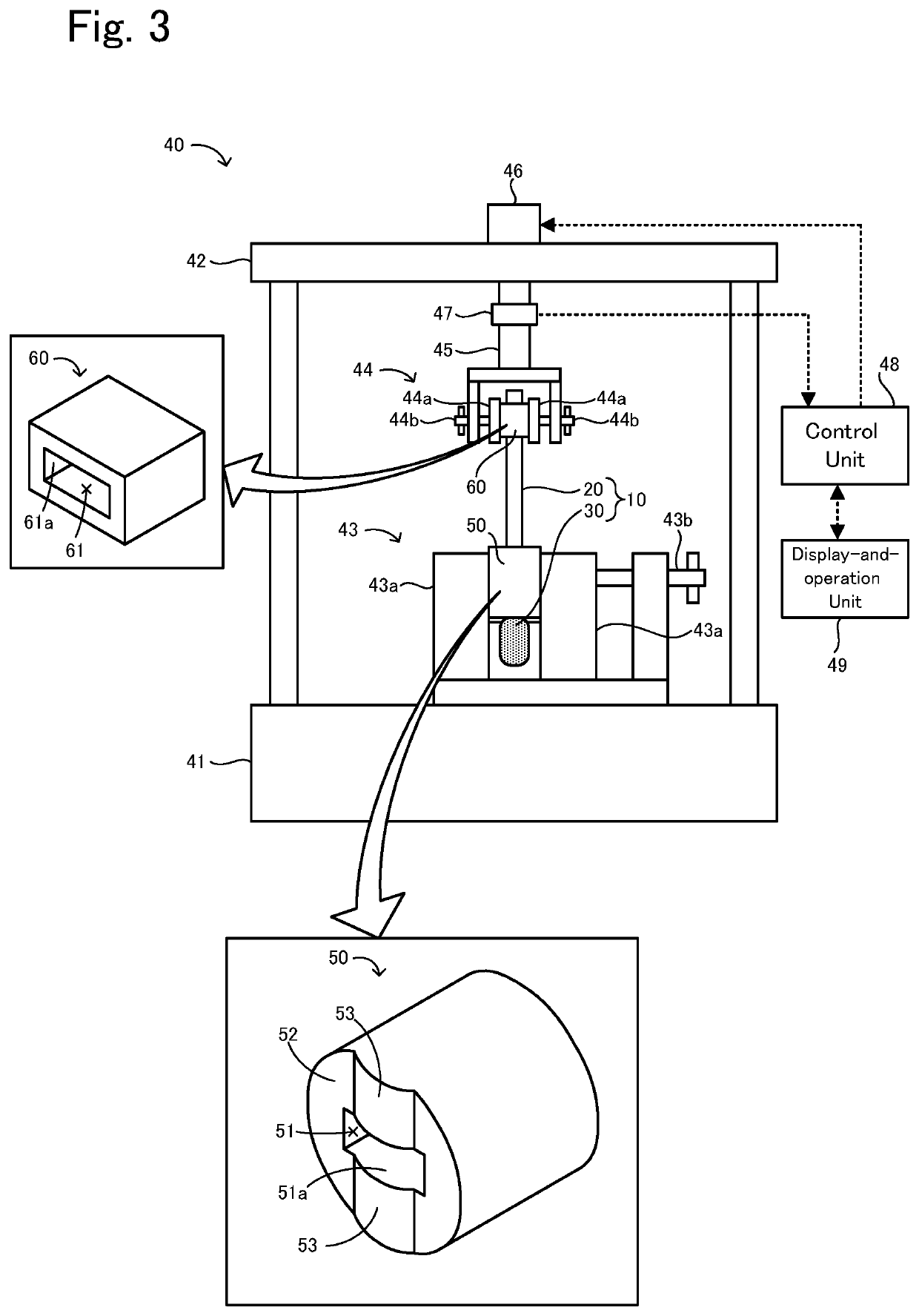
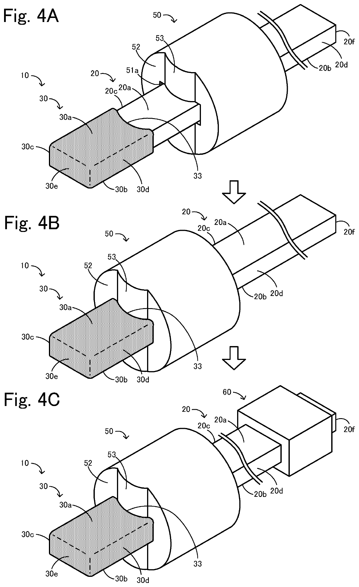
[0079]The adhesive-strength measurement including the steps (a) and (b) described above was conducted on each of the sensor elements A to E as Working Example 1. First, a peeling jig 50 and a holding jig 60 were prepared. The peeling jig 50 had a diameter of 8.7 mm, with a through hole 51 having an opening size of 1.7 mm by 4.6 mm and an axial length of 10 mm. The peeling jig 50 was made of SKD11. The projections 53 of the peeling jig 50 each had a height of 0.5 mm, the same as the depth of the recesses 33, so as to conform to the recesses 33. The holding jig 60 was shaped as a rectangular-parallelepiped body having a size of 3.45 mm by 6.25 mm by 14.5 mm. The through hole 61 had an opening size of 1.45 mm by 4.25 mm and an axial length of 14.5 mm. The holding jig 60 was made of NBR70. The hardness of the holding jig 60 that was measured with a type-A durometer in accordance with JIS K 6253-3:2012 was 70.

[0080]In the step (a), as with the case illustrated in FIGS. 4A to 4C, the peel...


PUM

PropertyMeasurementUnit
speedaaaaaaaaaa
speedaaaaaaaaaa
thicknessaaaaaaaaaa

Abstract

A method of measuring adhesive strength between an element body and a porous protection layer that are included in a sensor element includes (a) a step of holding a portion of the element body where the porous protection layer is absent with an elastic force exerted by a holding jig, and placing a peeling jig at a position between the porous protection layer and the holding jig in the longitudinal direction such that the element body is allowed to move in the longitudinal direction while the porous protection layer is prevented from moving in the longitudinal direction toward the holding jig; and (b) a step of moving, after the step (a), the peeling jig pushes the porous protection layer in the longitudinal direction, and measuring the adhesive strength of the porous protection layer.

Description

BACKGROUND OF THE INVENTION1. Field of the Invention[0001]The present invention relates to a method of measuring adhesive strength.2. Description of the Related Art[0002]There are hitherto known gas sensor elements that each detect the concentration of a specific gas, such as NOx, contained in a measurement-object gas, such as exhaust gas from an automobile. A known example of such a gas sensor element includes an element body and a porous protection layer that covers the surface of the element body (see PTL 1, for example).[0003]It is also known that, in a gas sensor element, the adhesive strength of a side conducting portion exposed to the outside on a side face of a multilayer body is measured by the Sebastian method (see PTL 2, for example). FIGS. 9A and 9B include schematic diagrams illustrating how the adhesive strength of a film 92 is measured by the Sebastian method. To measure the adhesive strength of the film 92 with respect to a substrate 91 by the Sebastian method, a stu...

Claims


Application Information

Patent Timeline
Patent Type & Authority Patents(United States)
IPC IPC(8): G01N19/04F16B11/00G01N27/407G01N27/403B29C65/48
CPCG01N19/04B29C65/48G01N27/403G01N27/407F16B11/006G01N2203/0091
Inventor ONISHI, RYOADACHI, YOSUKEHINO, TAKASHI
Owner NGK INSULATORS LTD
Why Eureka
Try Eureka