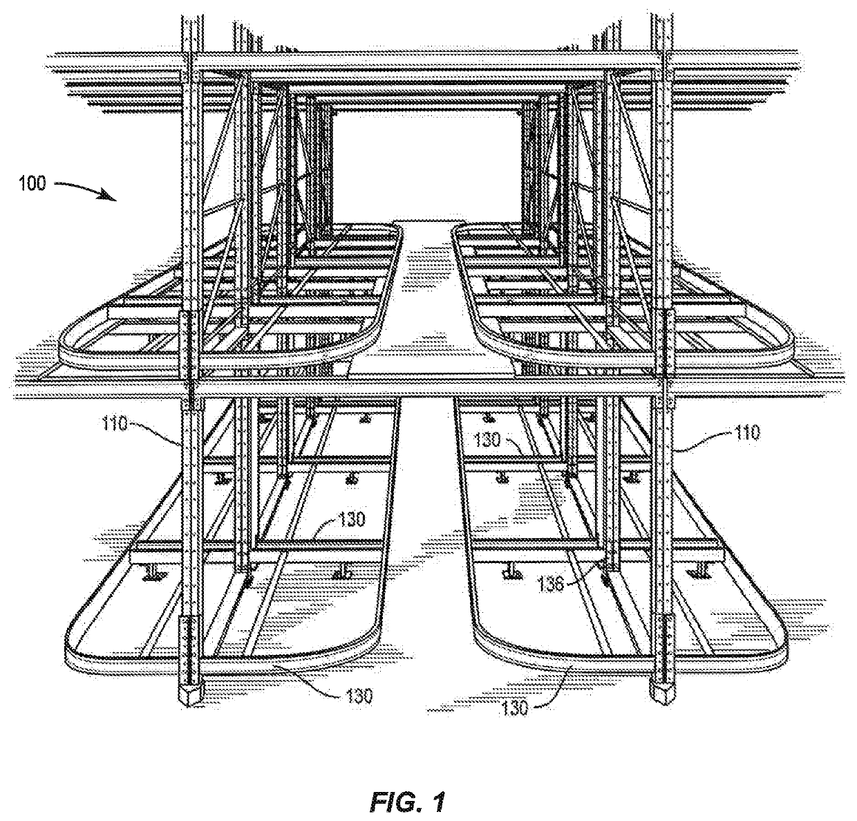
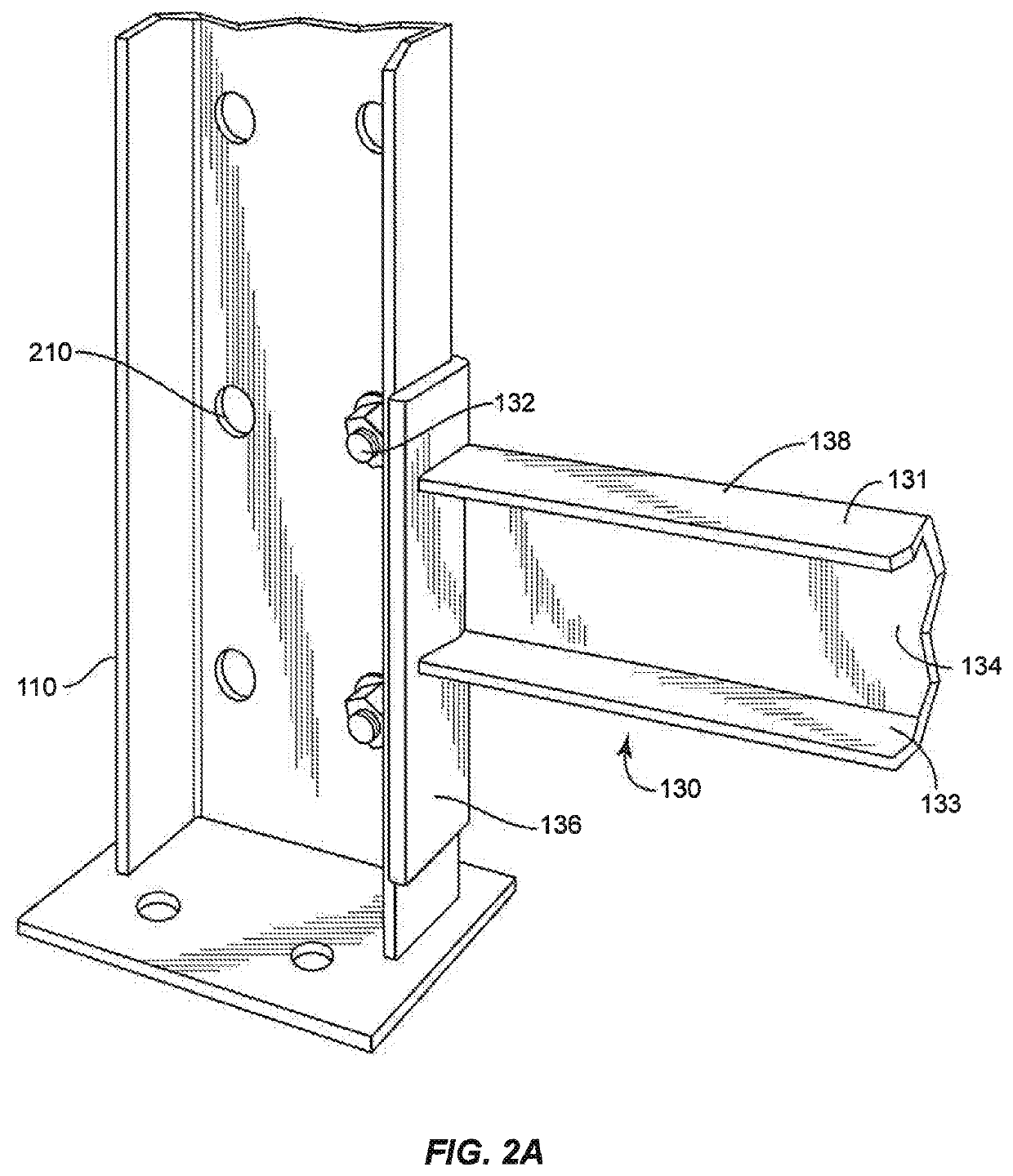
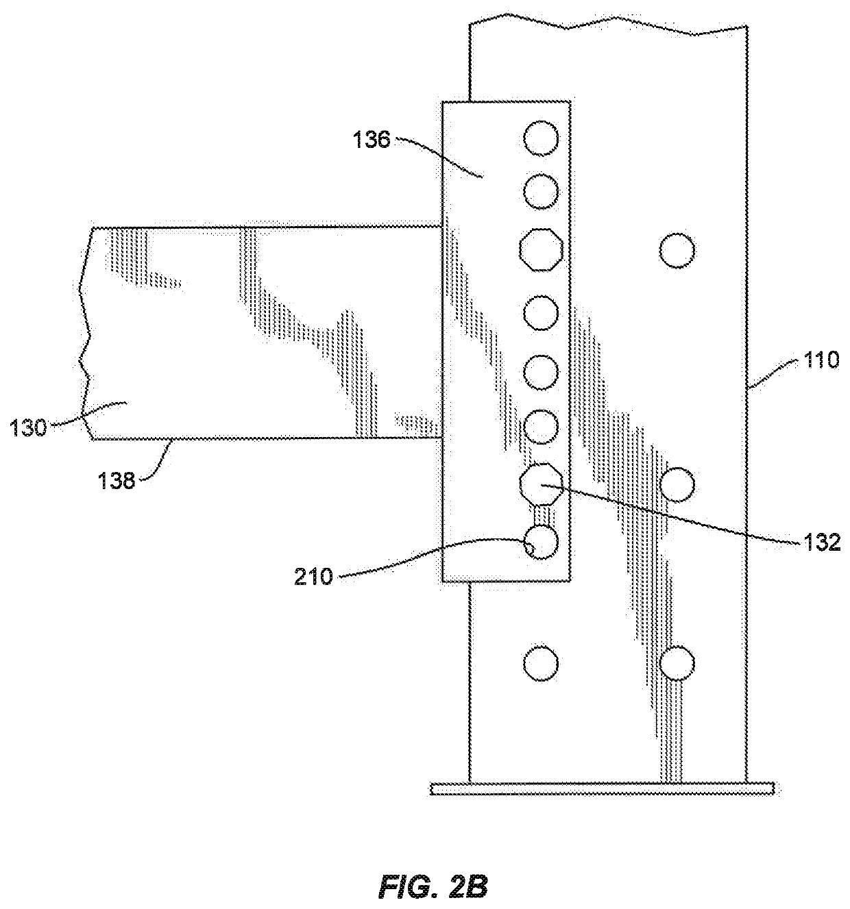
Structural member with stabilizing protrusions
a structural member and protruding technology, applied in the direction of sheet joining, fastening means, storage devices, etc., can solve the problems of inconvenient and not cost-effective horizontal beam fitting, inconvenient and proper assembly, and inconvenient construction of horizontal beams, so as to achieve tighter connection
- Summary
- Abstract
- Description
- Claims
- Application Information
AI Technical Summary
Benefits of technology
Problems solved by technology
Method used
Image

Examples
Embodiment Construction
[0020]The present disclosure may be understood more readily by reference to the following detailed description of the disclosure taken in connection with the accompanying figures, which form a part of this disclosure. It is to be understood that this disclosure is not limited to the specific devices, methods, conditions or parameters described and / or shown herein, and that the terminology used herein is for the purpose of describing particular embodiments by way of example only and is not intended to be limiting of the claimed disclosure.
[0021]Also, as used in the specification and including the appended claims, the singular forms “a,”“an,” and “the” include the plural, and reference to a particular numerical value includes at least that particular value, unless the context clearly dictates otherwise. Ranges may be expressed herein as from “about” or “approximately” one particular value and / or to “about” or “approximately” another particular value. When such a range is expressed, an...
PUM
 Abstract
Description
Claims
Application Information
 - R&D
- Intellectual Property
- Life Sciences
- Materials
- Tech Scout
- Unparalleled Data Quality
- Higher Quality Content
- 60% Fewer Hallucinations
Browse by: Latest US Patents, China's latest patents, Technical Efficacy Thesaurus, Application Domain, Technology Topic, Popular Technical Reports.
© 2025 PatSnap. All rights reserved.Legal|Privacy policy|Modern Slavery Act Transparency Statement|Sitemap|About US| Contact US: help@patsnap.com