
Monitoring system and monitoring method

a monitoring system and monitoring method technology, applied in the field of monitoring systems and monitoring methods, can solve the problems of crew members failing to judge priority and physical sensor not working, and achieve the effect of accurate trapping detection and easy and reliable monitoring

Active Publication Date: 2020-12-15
KOKUSA ELECTRIC CO LTD
View PDF19 Cites 1 Cited by
  • Summary
  • Abstract
  • Description
  • Claims
  • Application Information

AI Technical Summary

Benefits of technology

[0012]According to the present invention, by using trapping detection using image processing determination of monitoring videos in place of or in combination with the detection by physical sensors, more accurate trapping detection can be performed regardless of the type of object trapped. Further, from another viewpoint, a technique capable of realizing easier and more reliable monitoring can be provided by enabling a crew member to confirm the situation of the platform while viewing the video on a monitor installed in a crew room, in addition to the trapping detection method using the physical sensors and the image processing determination of monitoring videos, and by calling attention of the crew member with ringing of alarm in response to the detection of trapping.

Problems solved by technology

However, recently, when a thin component, such as a front wheel of a stroller is trapped, there are cases where the physical sensor does not work for detection of such a trapping and, as a result, a train start running as it is.
In this regard, even when the emergency stop button is pressed, the crew member may fail in judging the priority if the crew experience is insufficient and continue to let the train travel.

Method used


Image

  • Monitoring system and monitoring method
  • Monitoring system and monitoring method
  • Monitoring system and monitoring method

Examples


Embodiment Construction

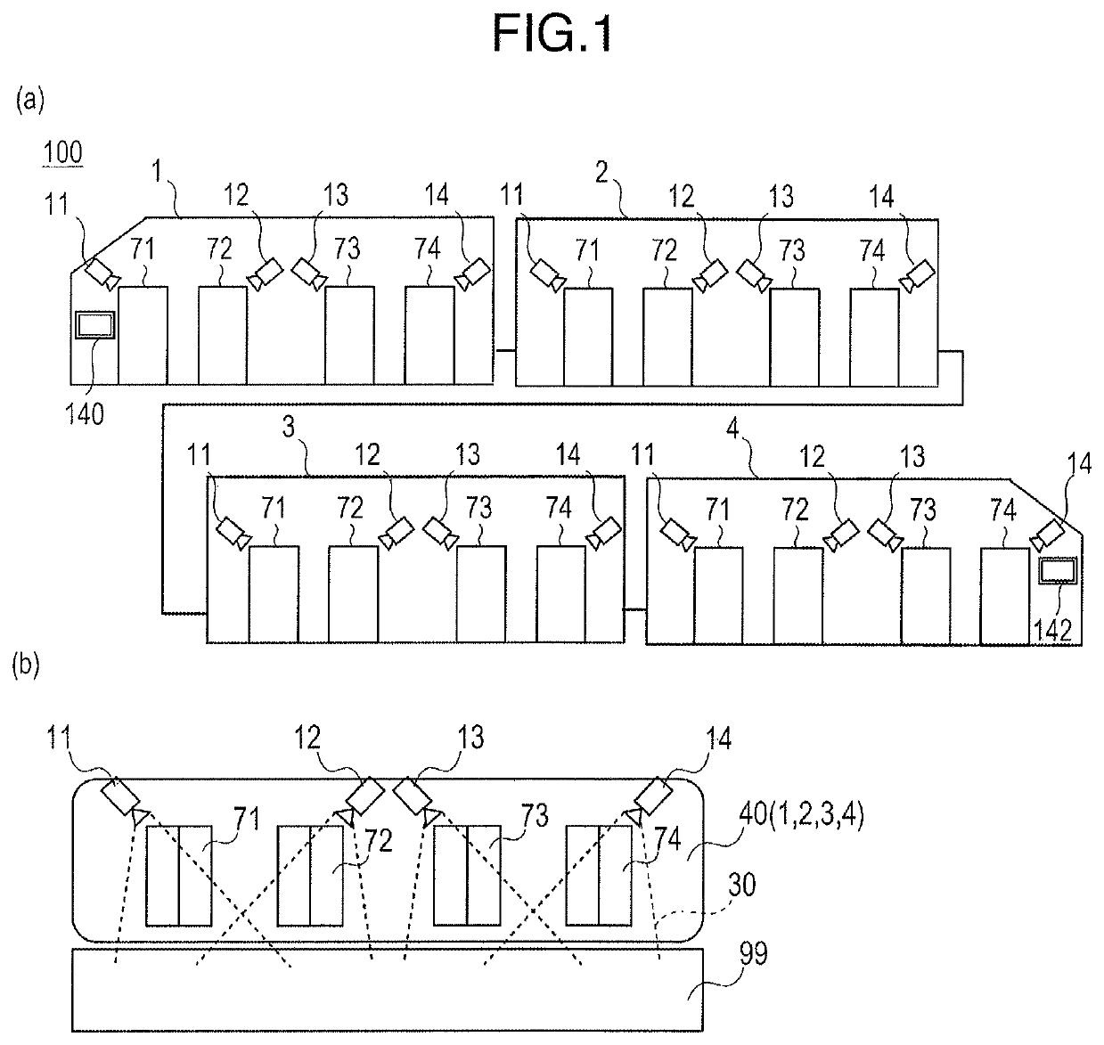
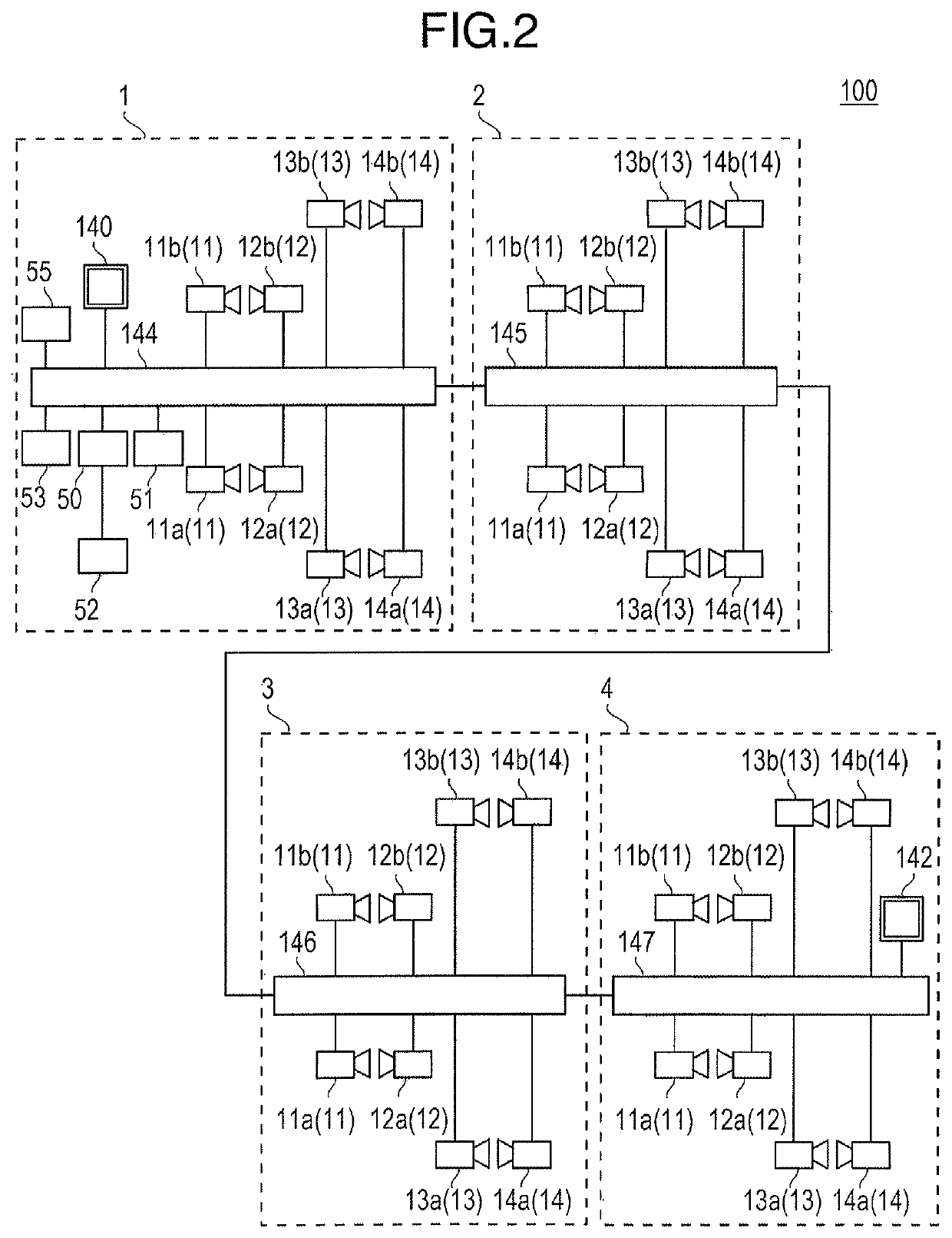
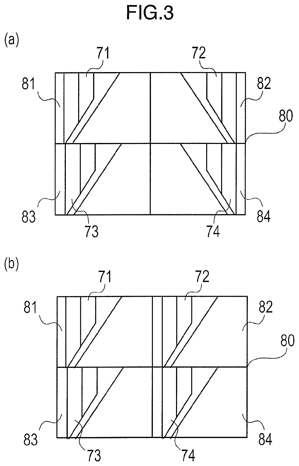
[0025]Next, the modes for carrying out the present invention (hereinafter, simply referred to as “embodiments”) will be specifically described with reference to the drawings. The outline of the present embodiment is as follows. (1) The image processing is performed based on videos of monitoring cameras that monitor vehicle doors, and it is discriminated whether an object located near the vehicle door is only passing near or is trapped by the vehicle door. (2) Videos of the monitoring cameras are allocated to a monitor installed in a crew room for monitoring, at prescribed timing, for example, when a train stops at the platform and the doors are opened. (3) When the vehicle doors are closed, trapping detection is performed based on image processing, and if trapping occurs, a corresponding video on the monitor is displayed in a display mode that draws attention easily, such as a display in a red frame, and further processing for ringing alarm sounds is performed.

[0026]The following ef...


PUM


Abstract

Provided is a technology for monitoring train doors which improves the accuracy of detection of trapping in vehicle doors. A server compares the difference between a static image (reference image 91), from each monitoring camera, of a normal state in which there is no trapping in vehicle doors, said static images being held in the server in advance, and a static image (an observation image 92) first acquired in a prescribed acquisition time. If a difference is present, the difference (difference image 94) between the reference image 91 and the observation image 92 acquired in the acquisition time is acquired. A quadrilateral F which covers the four sides of an object constituting the difference is subsequently rendered, the centre point of the quadrilateral is obtained, it is determined that trapping has occurred if movement of a centre coordinate C1, C2, . . . Cn, i.e. the difference between the centre coordinates C, is lower than a prescribed threshold value, and red frame rendering of video is indicated on a monitor.

Description

TECHNICAL FIELD[0001]The present invention relates to a monitoring system and a monitoring method, for example, to a system and a method for monitoring doors of a railway vehicle.BACKGROUND ART[0002]In railway monitoring, from the viewpoint of securing safety at the station platform (hereinafter, referred to as “platform”) as well as inside / outside of each vehicle, a system using monitoring cameras is known (see, for example, Patent Literatures 1 and 2). Also, in recent years, a railway monitoring system requires a vehicle door trapping detection technique for confirming whether there is any abnormality, such as trapping of a person or foreign body, in the vehicle doors when stopping at the platform and opening / closing vehicle doors, in addition to the monitoring of the inside / outside of the vehicle and the platform.[0003]As a main trapping detection method, a method for detecting the trapping of a person or foreign body in a vehicle door with a physical sensor using pressure or inf...

Claims


Application Information

Patent Timeline
Patent Type & Authority Patents(United States)
IPC IPC(8): H04N7/18B61K13/04H04N5/232B61B1/02
CPCH04N5/23218B61B1/02B61K13/04H04N7/183B61L15/0081B61L23/041H04N7/186H04N23/61
Inventor OHKI, KANA
Owner KOKUSA ELECTRIC CO LTD
Learn More