
System for monitoring flow of a matrix material in a molding tool using a scattering optical signal transmitted along at least one optical fiber during production of a component

a matrix material and optical signal technology, applied in the field of system and a method for monitoring an aircraft or spacecraft component, can solve the problems of inability to visual monitor the flow of matrix material, -based measuring systems do not provide continuous data on the actual advance of the front of the matrix material, etc., to achieve easy and reliable monitoring and easy and reliable monitoring of structural integrity.

Active Publication Date: 2017-01-03
AIRBUS OPERATIONS GMBH
View PDF10 Cites 7 Cited by
  • Summary
  • Abstract
  • Description
  • Claims
  • Application Information

AI Technical Summary

Benefits of technology

Enables continuous, accurate monitoring of matrix material flow and structural integrity during production and service, improving quality assurance and enabling immediate adjustments to production processes and post-production stress analysis.

Problems solved by technology

In the case of production of the component by an injection method with a closed molding tool, on the other hand, visual monitoring of the flow of matrix material is not possible, so sensors such as, for example ultrasonic sensors, line sensors that operate capacitively, temperature sensors and / or pressure sensors are employed.
Generally, however, these sensor-based measuring systems do not provide continuous data on the actual advance of the front of matrix material in real time as the sensors only detect changes in the corresponding physical quantities at discrete locations.

Method used


Image

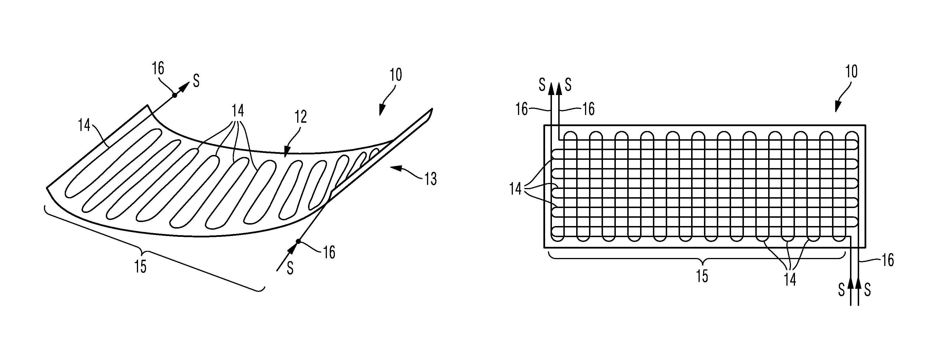
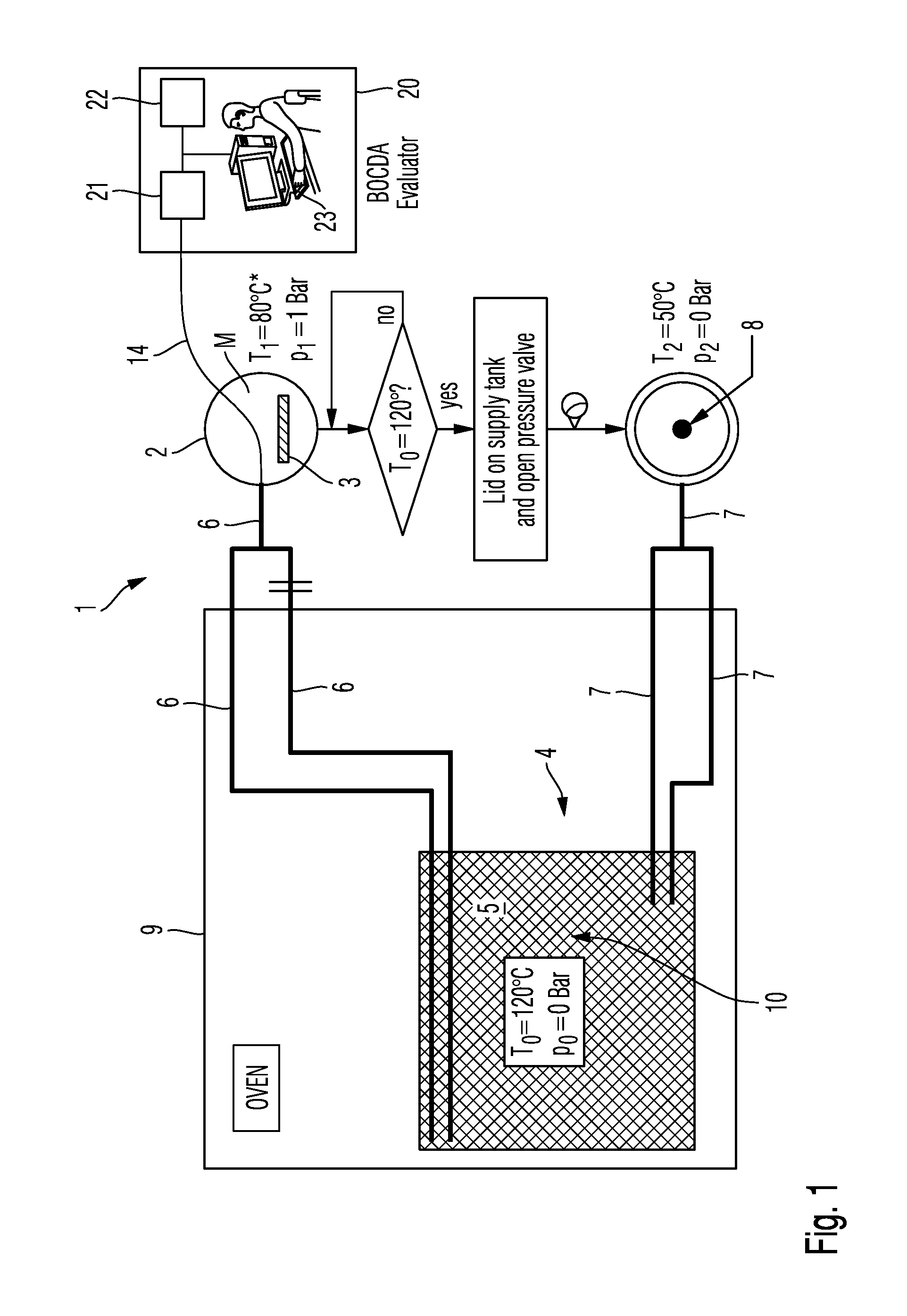
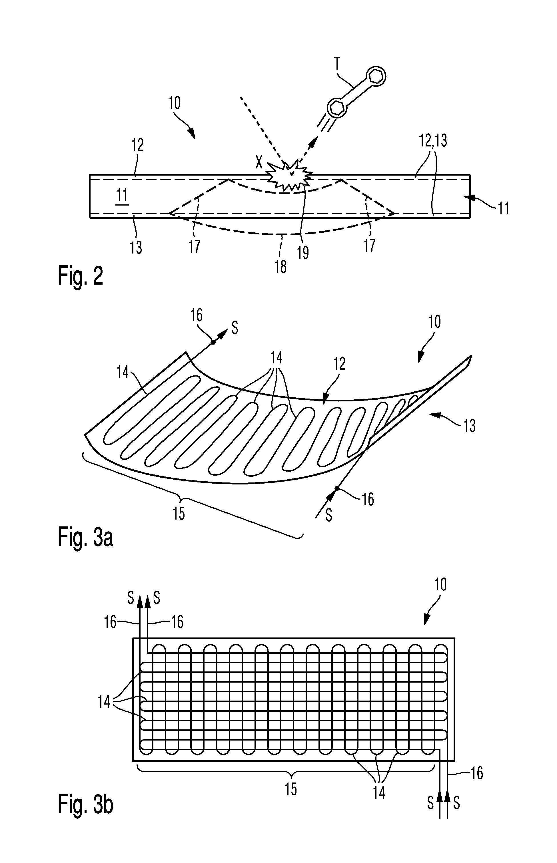
  • System for monitoring flow of a matrix material in a molding tool using a scattering optical signal transmitted along at least one optical fiber during production of a component
  • System for monitoring flow of a matrix material in a molding tool using a scattering optical signal transmitted along at least one optical fiber during production of a component
  • System for monitoring flow of a matrix material in a molding tool using a scattering optical signal transmitted along at least one optical fiber during production of a component

Examples


Embodiment Construction

[0065]The accompanying drawings are included to provide a further understanding of the present invention and are incorporated in and constitute a part of this specification. The drawings illustrate particular embodiments of the invention and together with the description serve to explain the principles of the invention. Other embodiments of the invention and many of the attendant advantages of the invention will be readily appreciated as they become better understood with reference to the following detailed description.

[0066]It will be appreciated that common and well understood elements that may be useful or necessary in a commercially feasible embodiment are not necessarily depicted in order to facilitate a less abstracted view of the embodiments. The elements of the drawings are not necessarily illustrated to scale relative to each other. It will further be appreciated that certain actions and / or steps in an embodiment of a method may be described or depicted in a particular orde...


PUM

PropertyMeasurementUnit
pressureaaaaaaaaaa
temperatureaaaaaaaaaa

Abstract

A system for monitoring a fiber-reinforced composite component in production or in service. The system includes a composite component having reinforcing fibers which are encompassed by a matrix material; at least one optical fiber arranged to extend in a continuous path over a monitoring area of the composite component for contact with the matrix material; a signal generator configured to transmit an optical signal along the at least one optical fiber; and a detector device configured to detect scattering, and in particular backscattering, of the optical signal transmitted along the at least one optical fiber.

Description

CROSS-REFERENCES TO RELATED APPLICATIONS[0001]This application claims the benefit of the U.S. Provisional Application No. 61 / 655,507, filed on Jun. 5, 2012, and of the European patent application No. 12170869.7 filed on Jun. 5, 2012, the entire disclosures of which are incorporated herein by way of reference.FIELD OF THE INVENTION[0002]The present invention relates to a system and a method for monitoring an aircraft or spacecraft component in production and / or in service, especially a fiber-reinforced composite component, and particularly for quality assurance of the component. The invention further relates to a component, particularly a fiber-reinforced composite, of an aircraft or spacecraft that is suitable for use in such a system or method, especially as a structural or load-bearing member.BACKGROUND OF THE INVENTION[0003]Efforts are being made in aircraft construction to employ components on an increasing scale that consist completely or at least partly of fiber-reinforced com...

Claims


Application Information

Patent Timeline
Patent Type & Authority Patents(United States)
IPC IPC(8): G01J1/04G01N21/85G01L1/24G01M5/00B29C70/54G01D5/353G01K11/32G01M11/08
CPCB29C70/546G01D5/35358G01L1/242G01M5/0091G01K11/32G01M11/083
Inventor ZUARDY, ICHWAN M.ZAHLEN, PIERRE C.BOCKENHEIMER, CLEMENSBULLINGER, OLIVER
Owner AIRBUS OPERATIONS GMBH
Learn More