
System and method for evacuating a process room

A space, external air technology, applied in the direction of pump combination for elastic fluid rotary piston type/oscillating piston type, non-variable displacement pump, radial flow pump, etc., can solve the problem of taking too long

Active Publication Date: 2020-08-07
MAN ENERGY SOLUTIONS SA
View PDF9 Cites 0 Cited by
  • Summary
  • Abstract
  • Description
  • Claims
  • Application Information

AI Technical Summary

Problems solved by technology

Especially when a vacuum pump is used to evacuate the process space, this can take too long in the case of process spaces with large volumes to be evacuated

Method used


Image

  • System and method for evacuating a process room
  • System and method for evacuating a process room

Examples


Embodiment Construction

[0043] The invention relates to a system and a method for evacuating a process space, in particular a process space with a large volume.

[0044] Large volume process space means the volume to be evacuated is more than 10,000 m 3 , especially more than 20,000 m 3 The order of magnitude of the process space.

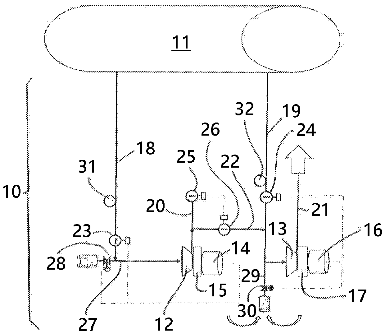
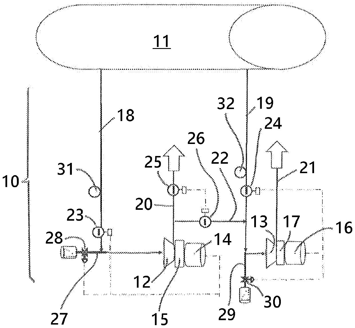
[0045] figure 1 with figure 2 Each shows a schematic block diagram of a system 10 for evacuating a process space 11 in two different operating states.

[0046] The system 10 for evacuating a process space 11 has a first compressor 12 and a second compressor 13 .

[0047] The first compressor 12 is driven by an electric motor 14 which transmits driving power to the first compressor 12 via a transmission 15 . The second compressor 13 is similarly driven by an electric motor 16 which transmits drive power to the second compressor 13 via a transmission 17 .

[0048] The first compressor 12 may be coupled to the process space 11 via a first inflow line 18 . The second ...


PUM


Abstract

The invention relates to a system and a method for evacuating a process space (11) by initially evacuating the process space (11) to a pressure limit value using two compressors (12,13) operated in parallel, and on reaching or undershooting the pressure limit value, the process space (11) is subsequently evacuated using the two compressors (12,13) operated in series.

Description

technical field [0001] The invention relates to a system for evacuating a process space. Furthermore, the invention relates to a method for evacuating a process space. Background technique [0002] From practice, various applications are known in which the process space must be evacuated. For this purpose, vacuum pumps have hitherto been used. Especially when a vacuum pump is used to evacuate the process space, this can take too long in the case of process spaces with a relatively large volume to be evacuated. Therefore, there is a need for a new system and method for evacuating process spaces, by means of which, in particular, relatively large process spaces can be reliably evacuated within a short time. Contents of the invention [0003] Starting from this point, the object of the present invention is to create a novel system and method for evacuating a process space. [0004] This object is achieved by a system for evacuating a process space according to claim 1 . ...

Claims


Application Information

Patent Timeline
Patent Type & Authority Applications(China)
IPC IPC(8): F04B37/14F04B41/06F04B49/03F04B49/02F04B49/00
CPCF04B37/14F04B41/06F04B49/03F04B49/02F04B49/00F04C25/02F04C23/001F04B49/06F04B49/22F04B2205/01F04B2205/16F04B49/007F04B25/00F04B49/022F04B23/00F04D15/0072F04D17/14F04D27/0269
Inventor G.贝米希
Owner MAN ENERGY SOLUTIONS SA
Learn More