
Predictive eye tracking systems and methods for variable focus electronic displays

a technology of eye tracking and electronic displays, applied in the field of immersive viewing, can solve problems such as visual fatigue and nausea, problems such as the failure of existing headsets to correctly display simulated three-dimensional, and the inability to accurately display simulated three-dimensional

Active Publication Date: 2020-12-22
META PLATFORMS TECH LLC
View PDF11 Cites 15 Cited by
  • Summary
  • Abstract
  • Description
  • Claims
  • Application Information

AI Technical Summary

Benefits of technology

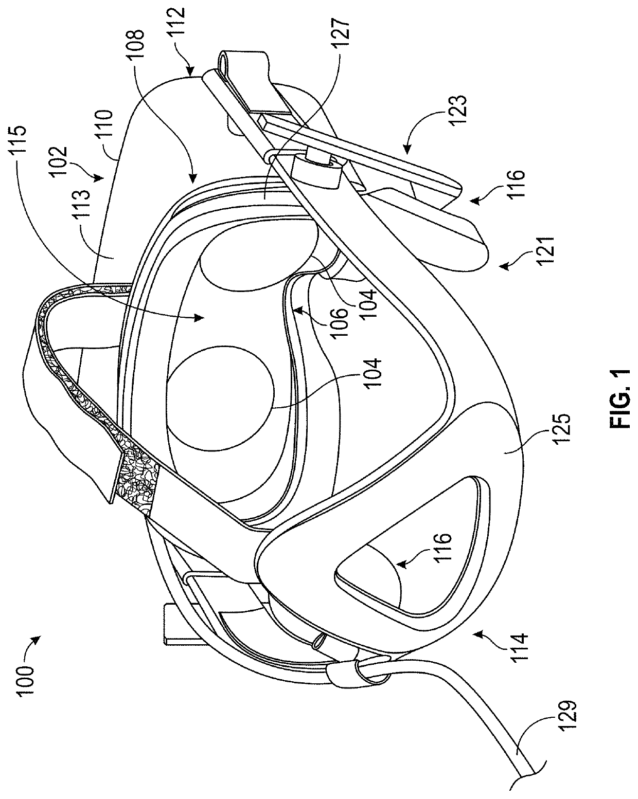
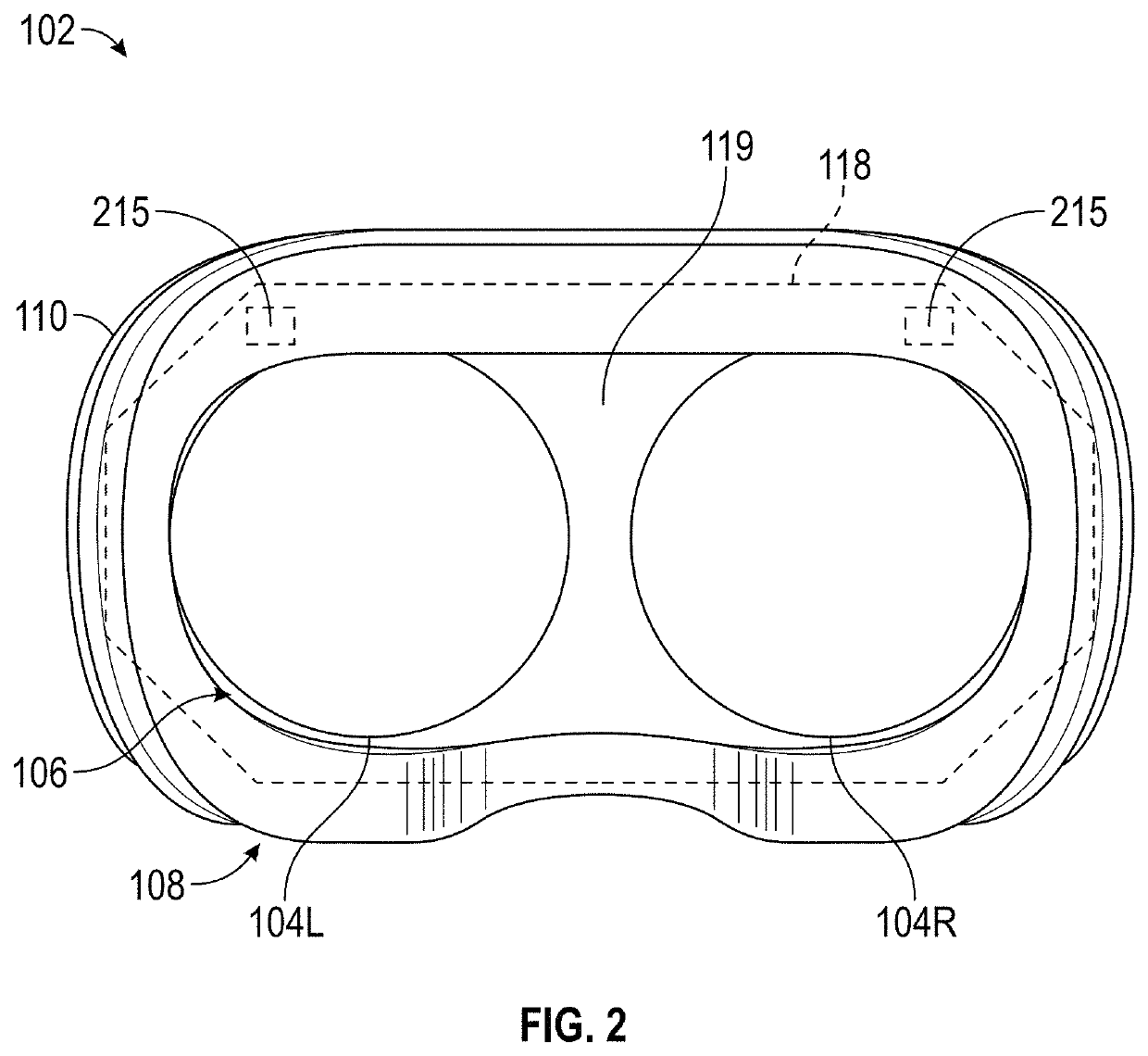
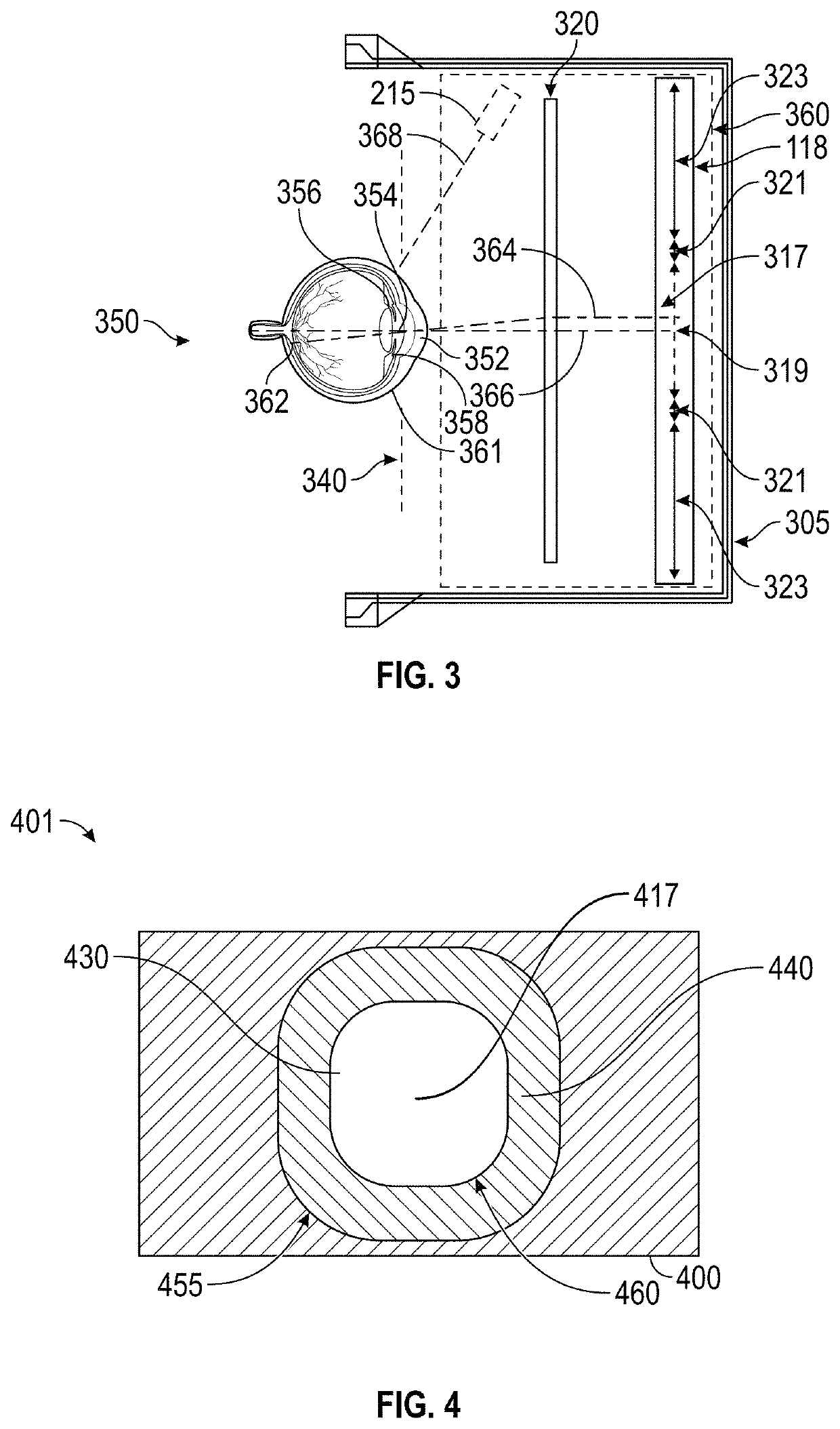
The present patent provides head-mountable display systems with predictive eye tracking for virtual reality, augmented reality, and mixed reality content. The systems include an eye tracking unit, an eye prediction module, and a processing circuitry. The eye tracking unit obtains eye tracking data, the eye prediction module identifies a change in the current gaze location, and the eye prediction module generates a predicted future gaze location. The processing circuitry then renders a predictive foveated display image frame based on the predicted future gaze location. The technical effect of this technology is to provide a more immersive and realistic user experience for head-mountable display devices.

Problems solved by technology

However, challenges can arise when presenting simulated three-dimensional content that changes with the changing head and eye position of the user.
For example, such a simulation can, in some circumstances, cause visual fatigue and nausea resulting from an inability of existing headsets to correctly render or otherwise compensate for vergence and accommodation conflicts.
Though the eye receives data from a field of about 200 degrees, the acuity over most of that range is poor.
Accordingly, some of the resources (e.g., power, memory, processing time, etc.) that went into generating the high resolution image being viewed by the user is wasted as the user is not able to perceive the portion of the image light imaged outside the fovea at its full resolution.
However, it can be additionally challenging to integrate the operations of advanced display features, such as variable focus display features and foveated display features, with other portions of a display pipeline, from content generation to content display.

Method used


Image

  • Predictive eye tracking systems and methods for variable focus electronic displays
  • Predictive eye tracking systems and methods for variable focus electronic displays
  • Predictive eye tracking systems and methods for variable focus electronic displays

Examples


example eye

Prediction Components and Methods for Head-Mountable Display Devices

[0112]FIG. 8 illustrates a schematic diagram of an exemplary implementation of eye prediction module 722. As shown, eye prediction module 722 may include a filtering module 800, a gaze prediction module 802, and a vergence prediction module 804. Filtering module 800 may receive eye tracking data 814 (e.g., a current gaze direction, a current gaze direction of motion, and a current gaze speed of motion for each eye, and / or other eye tracking data such as current and / or past raw position and / or orientation data for one or more parts of each of the user's eye) from eye tracking module 710, and may output predictions such as predicted gaze locations and / or predicted vergence planes.

[0113]Filtering module 800 may also receive other data such as user calibration data 816, scene content information 818, and / or head tracking data 820. User calibration data 816 may be obtained in, for example, a training session for each par...


PUM


Abstract

Various aspects of the subject technology relate to prediction of eye movements of a user of a head-mountable display device. Predictive foveated display systems and methods, using the predicted eye movements are also disclosed. Predictive variable focus display systems and methods using the predicted eye movements are also disclosed. Predicting eye movements may include predicting a future gaze location and / or predicting a future vergence plane for the user's eyes, based on the current motion of one or both of the user's eyes. The predicted gaze location may be used to pre-render a foveated display image frame with a high-resolution region at the predicted gaze location. The predicted vergence plane may be used to modify an image plane of a display assembly to mitigate or avoid a vergence / accommodation conflict for the user.

Description

BACKGROUNDField[0001]The present disclosure generally relates to display systems for immersive viewing and, more particularly, to predictive eye tracking for head-mountable display devices.Description of the Related Art[0002]Head-mounted displays (HMDs) can include display panels such as liquid crystal display panels, light-emitting diode display panels, or wave guide displays that can be used to display virtual reality, augmented reality, or mixed reality environments to a user. For example, stereoscopic images can be displayed on an electronic display inside the headset to simulate the illusion of depth. Head tracking sensors and eye tracking sensors can be used to estimate what portion of the virtual environment is being currently viewed by the user, to determine which portion of the environment to present on the display. However, challenges can arise when presenting simulated three-dimensional content that changes with the changing head and eye position of the user.[0003]For exa...

Claims


Application Information

Patent Timeline
Patent Type & Authority Patents(United States)
IPC IPC(8): G06F3/01G02B27/01G02B27/00G06T19/00
CPCG02B27/0189G02B27/0172G06F3/013G06T19/006G02B27/0093G02B2027/0187G02B2027/011G02B27/0176G02B2027/0134G06F3/011
Inventor SZTUK, SEBASTIANSAN AGUSTIN LOPEZ, JAVIERLANSEL, STEVEN PAUL
Owner META PLATFORMS TECH LLC
Learn More