Systems and methods for simulating contact between physical objects

Active Publication Date: 2020-12-29
HEXAGON MFG INTELLIGENCE INC
View PDF11 Cites 1 Cited by
  • Summary
  • Abstract
  • Description
  • Claims
  • Application Information

AI Technical Summary

Benefits of technology

[0004]Embodiments of the methods and systems described herein perform simulation of structures such as pipes, beams, etc. to capture their behavior when they are in contact with each other or when they are in contact with either rigid or deformable bodies using the Finite Element Method (FEM). The objective of the numerical simulations is to determine the deformed geometry, the reaction or contact forces between parts, the transfer of state quantities (temperature, current, etc) and the strains and stresses in the part to ensure safe, reliable and optimal part design. Pipes and beams and similar long and slender structures are us

Problems solved by technology

High levels of accuracy can require more computational

Method used


Image

  • Systems and methods for simulating contact between physical objects
  • Systems and methods for simulating contact between physical objects
  • Systems and methods for simulating contact between physical objects

Examples


Embodiment Construction

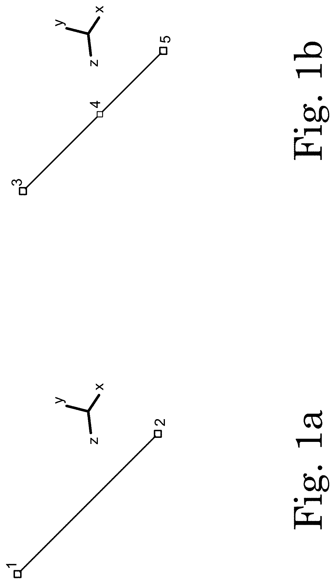
[0032]The numerical simulation of beams and pipes are performed using three dimensional beam (3-D) elements in one embodiment. These elements as represented in FIGS. 1a and 1b and are geometrically represented by either two or three nodes (e.g., nodes 1, 2, or 3), and these nodes in the finite element sense are described by their three coordinate positions X, Y and Z. Each node in FIG. 1a has six degrees of freedom Ux, Uy, Uz, θx, θy, and θz. In certain formulations an additional degree of freedom representing the twist is also represented. The numerical behavior of these beams or pipes is governed by their shape functions. The technique described below is suitable for all three dimensional beam, pipe or other elements. Furthermore, these three dimensional representations are often simplified to represent two dimensional (2-D) beam or shell behavior. A user may simulate contact between two objects by using a computer-aided design (CAD) geometry for use in computer-aided engineering ...


PUM


Abstract

The method generates a simulated object represented by finite elements each comprising two or more nodes that represent a first physical object, the first simulated object comprising a plurality of segments placed adjacent to each other to form a surface of the first simulated object. The method further includes generating a second simulated object. The method determines the distance between individual segments of the first simulated object and the plurality of segments of the second simulated object. The method determines a stiffness matrix and force vectors for the at least one segment of the first simulated object that is in contact with at least one segment of the second simulated object. The method transforms the stiffness matrix and the force vector from the segments to determine a stiffness matrix and a force vector on the two or more nodes of the finite element representation of the physical objects.

Description

CROSS-REFERENCE TO RELATED PATENT APPLICATIONS[0001]This application is a Continuation-In-Part of U.S. application Ser. No. 13 / 625,807, filed Sep. 24, 2012, incorporated herein by reference in its entirety.BACKGROUND[0002]Manufacturing complex systems and products usually include creating computer-aided design models and conducting numerical tests on the models to determine their behavior. Generating a functional model is a time-consuming process and reducing the amount of time for creating a model and performing the simulation is beneficial to any product manufacturer.[0003]During the computer aided design (CAD) and / or computer-aided engineering (CAE) geometry modeling process, a user may wish to determine how two or more shapes or bodies may interact with each other under external loads as well as their resultant behavior.SUMMARY OF THE DISCLOSURE[0004]Embodiments of the methods and systems described herein perform simulation of structures such as pipes, beams, etc. to capture the...

Claims


Application Information

Patent Timeline
IPC IPC(8): G06F17/13G06F30/23G06F111/10
CPCG06F30/23G06F17/13G06F2111/10G06F2119/14
Inventor GELTEN, CEESBOUT, ADRIE
Owner HEXAGON MFG INTELLIGENCE INC
Why Eureka
Try Eureka