
Method and system for splicing nose wire in a facemask manufacturing process

a manufacturing process and nose wire technology, applied in the field of protective facemasks, can solve the problems of high cost and far short of estimated goals, and achieve the effect of preventing such kinking or twisting, minimizing the possibility of twisting or kinking or the wir

Active Publication Date: 2021-01-05
OWENS & MINOR INC +3
View PDF102 Cites 0 Cited by
  • Summary
  • Abstract
  • Description
  • Claims
  • Application Information

AI Technical Summary

Benefits of technology

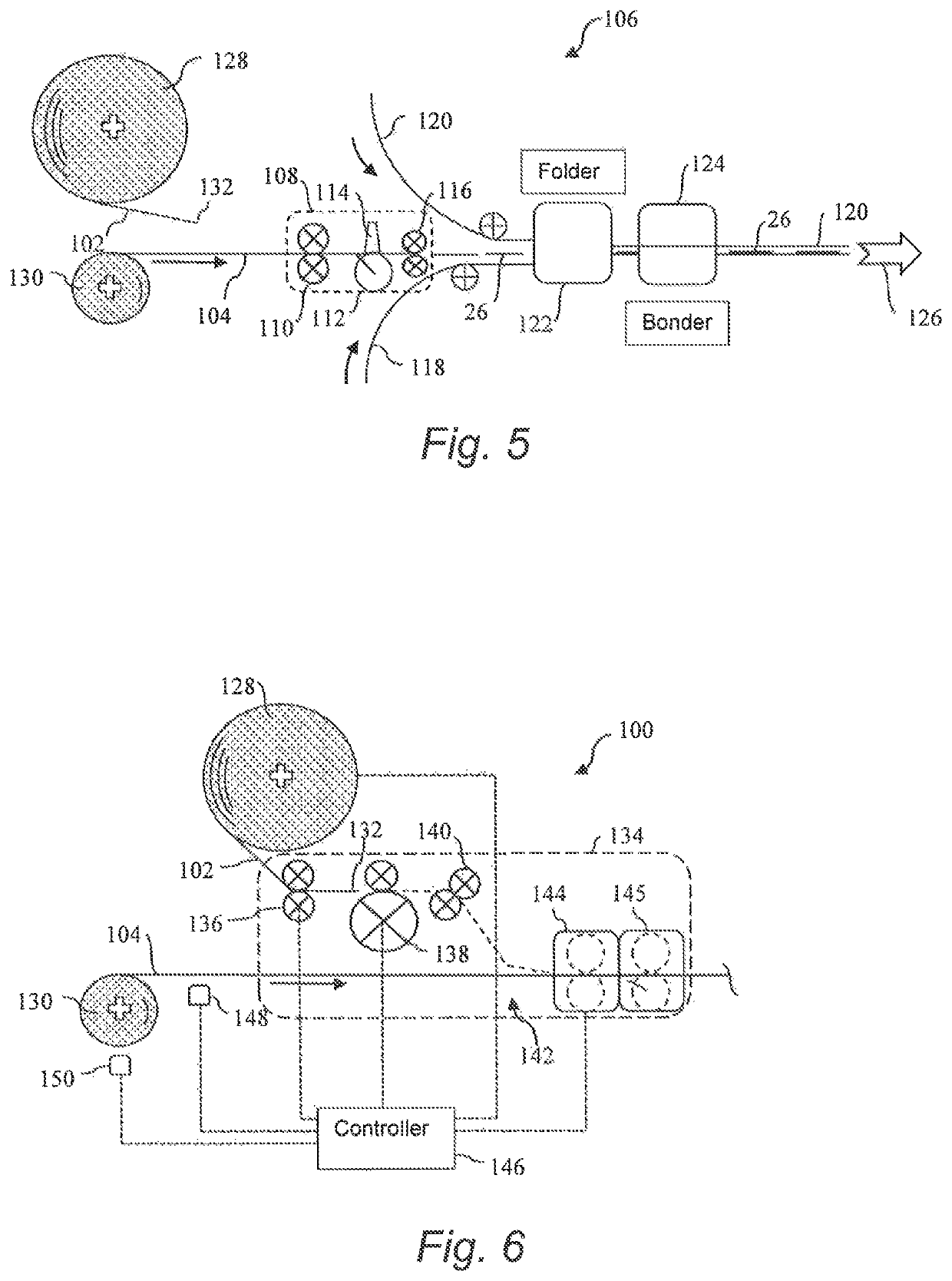
This patent text describes a way to create a steady supply of wire for a manufacturing process. By starting with a reserve roll of wire and using feed rollers to speed up the wire, the process can quickly reach the desired speed without having to fully accelerate the entire reserve roll. This reduces wear and tear on the wire and ensures a smooth manufacturing process. A guide is used to prevent the wire from kinking or twisting during the accumulation process, allowing for a smooth and unobstructed flow of wire.

Problems solved by technology

This is an extremely expensive undertaking.
Current facemask production lines are capable of producing only about 100 masks / minute due to technology and equipment restraints, which falls far short of the estimated goal.

Method used


Image

  • Method and system for splicing nose wire in a facemask manufacturing process
  • Method and system for splicing nose wire in a facemask manufacturing process
  • Method and system for splicing nose wire in a facemask manufacturing process

Examples


Embodiment Construction

[0040]Reference now will be made in detail to various embodiments of the invention, one or more examples of which are set forth below. Each example is provided by way of explanation of the invention, not limitation of the invention. In fact, it will be apparent to those skilled in the art that various modifications and variations may be made in the present invention without departing from the scope or spirit of the invention. For instance, features illustrated or described as part of one embodiment, may be used on another embodiment to yield a still further embodiment. Thus, it is intended that the present invention covers such modifications and variations as come within the scope of the appended claims and their equivalents.

[0041]As mentioned, the present methods relate to splicing of a reserve nose wire to a running nose wire in a facemask production line. The downstream facemask production steps are not limiting aspects of the invention and, thus, will not be explained in great d...


PUM


Abstract

A method and system are provided for splicing a reserve nose wire to a running nose wire in a facemask production line. Prior to depletion of the running nose wire, a reserve nose wire is brought up to a transport speed in a conveying direction of the running nose wire. At or near a zero relative speed between the running nose wire and the reserve nose wire, a leading end of the reserve nose wire is introduced onto the running nose wire, and the two wires are spliced together. The running nose wire is then cut upstream of the splice location such that the reserve nose wire becomes a new running nose wire in the production line.

Description

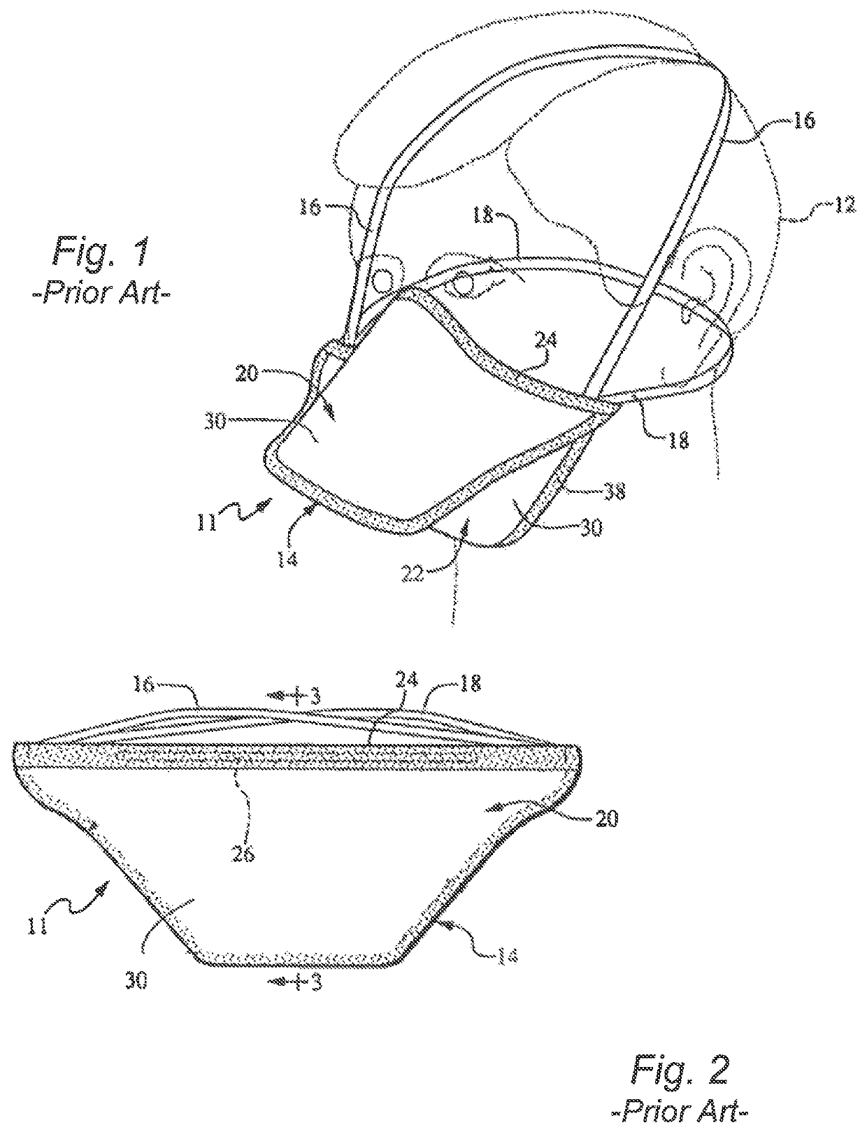
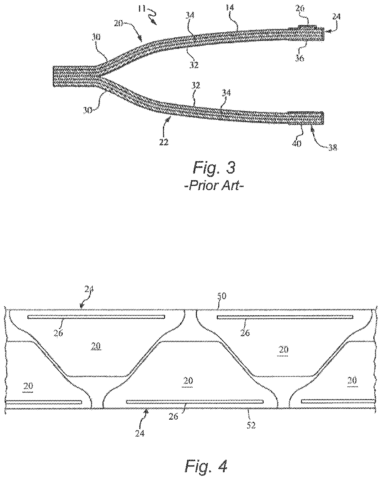
FIELD OF THE INVENTION[0001]The present invention relates generally to the field of protective facemasks, and more specifically to a method and system for splicing nose wire supplies in the manufacturing line of such facemasks.FAMILY OF RELATED APPLICATIONS[0002]The present application is related by subject matter to the following concurrently filed PCT applications (all of which designate the US):[0003]International Application No.: PCT / US2015 / 055858; entitled “Method and System for Splicing Nose Wire in a Facemask Manufacturing Process”.[0004]a. International Application No.: PCT / US2015 / 055861; entitled “Method and System for Splicing Nose Wire in a Facemask Manufacturing Process”.[0005]b. International Application No.: PCT / US2015 / 055863; entitled “Method and System for Introducing a Reserve Nose Wire in a Facemask Production Line”.[0006]c. International Application No.: PCT / US2015 / 055865; entitled “Method and System for Cutting and Placing Nose Wires in a Facemask Manufacturing P...

Claims


Application Information

Patent Timeline
Patent Type & Authority Patents(United States)
IPC IPC(8): B65H69/06A62B23/02B65H69/00
CPCB65H69/06A62B23/025B65H69/00B65H2701/36
Inventor PAMPERIN, MARK THOMASHARRIS, NATHAN CRAIGWEBER, JOSEPH P.HOUDE, AJAY Y.HARRINGTON, DAVID LAMAR
Owner OWENS & MINOR INC
Learn More