

Electric rail carriage
a technology of electric rail carriages and rails, applied in the direction of batteries/cells, cell components, battery/cell propulsion, etc., can solve the problems of train no longer being able to move, engine or generator failure, and significant delay for passengers
- Summary
- Abstract
- Description
- Claims
- Application Information
AI Technical Summary
Benefits of technology
Problems solved by technology
Method used
Image

Examples
Embodiment Construction
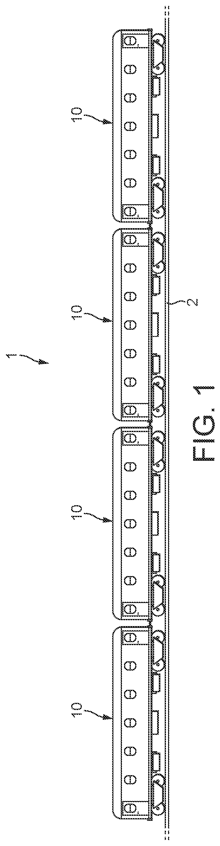
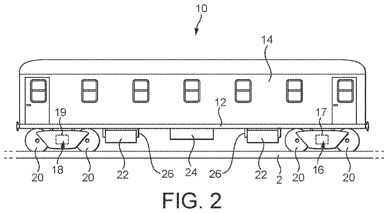
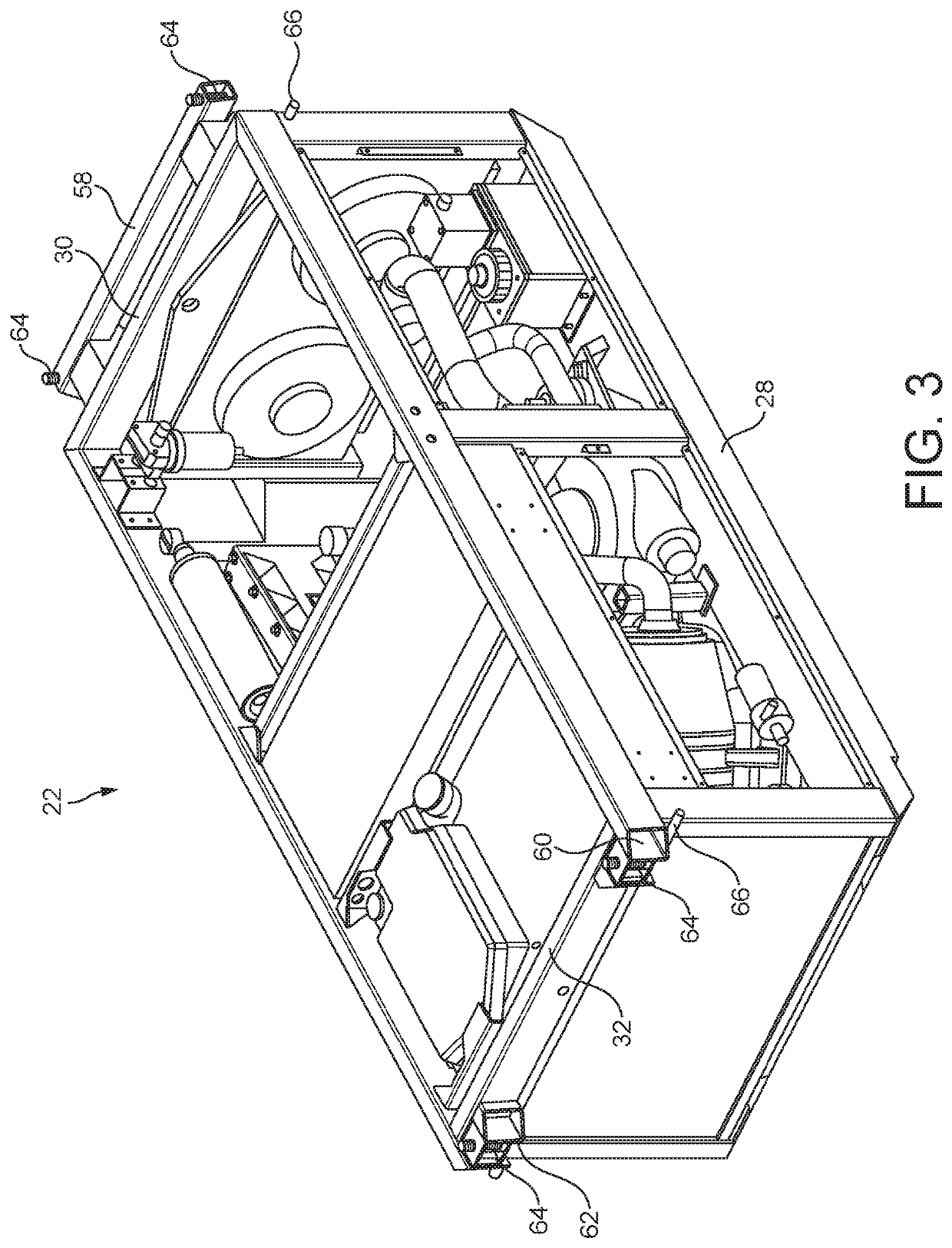
[0007]According to an aspect there is provided an electric rail carriage arranged to be powered by at least one power module which is arranged to generate electric power, the carriage comprising: a main chassis; and at least one power module bay located underneath the main chassis and within which a power module can be removably located and secured such that the power module is supported underneath the main chassis. This arrangement may allow a power module can be quickly and easily installed within and removed from a power module bay.
[0008]In this specification the term “electric rail carriage” should be understood to mean a rail carriage which is arranged to be driven by an electric motor. Thus, the electric rail carriage comprises an electric motor which can drive the wheels of the carriage. The electric motor may be supplied with power from any suitable source such as a battery, a fuel cell, or an electric generator, for example. A power module arranged to generate electric powe...
PUM
| Property | Measurement | Unit |
|---|---|---|
| electric power | aaaaa | aaaaa |
| power | aaaaa | aaaaa |
| distance | aaaaa | aaaaa |
Abstract
Description
Claims
Application Information