[0008]In contrast to the prior art, the glaucoma drainage implant according to the invention provides the advantage that fibrotic encapsulation can be prevented by the actuation area provided in the pressure relief flap. It is now possible to reduce or indeed to completely avoid any undesired functional restriction of the pressure relief valve by mobilizing it non-invasively. It is also possible, advantageously, to forego the use of cytotoxins, such as mitomycin C or 5-fluoruracil, and thus prevent feared, late-onset sterile endophthalmitis.
[0011]In the context of the present invention, with regard to an actuation area designed as a thermomechanically active area, mobilization of the pressure relief flap should be understood as opening the pressure relief flap by inputting an amount of heat into said area effectively, and automatic closure of the pressure relief flap after extraction of the heat from the thermomechanically active area. Alternatively, the pressure relief flap can be opened by an amount of heat which is effectively extracted from the area, and automatic closure of the pressure relief flap can be realized accordingly by re-inputting the heat into that area.
[0009]In one preferred variant, the actuation area has a thermomechanically active area, which allows the pressure relief flap to be mobilized non-invasively by a change in temperature. The actuation area is preferably provided in the form of a shape-memory material or includes such a material. The shape-memory material advantageously has a two-way memory effect. The shape-memory material may be a shape-memory polymer or a shape-memory alloy or include such a polymer or alloy.
[0010]In the context of the present invention, mobilizing the pressure relief flap should be understood as opening the pressure relief flap by inputting heat in the vicinity of the pressure relief flap and as automatic closing of the pressure relief flap on cooling. Automatic closing need not necessarily mean complete closure of the pressure relief flap. Rather, the implant or the pressure relief flap can be designed in such a way that it adopts a slightly open condition on cooling, depending on requirements, in order to allow aqueous humor to drain sufficiently.
[0011]In the context of the present invention, with regard to an actuation area designed as a thermomechanically active area, mobilization of the pressure relief flap should be understood as opening the pressure relief flap by inputting an amount of heat into said area effectively, and automatic closure of the pressure relief flap after extraction of the heat from the thermomechanically active area. Alternatively, the pressure relief flap can be opened by an amount of heat which is effectively extracted from the area, and automatic closure of the pressure relief flap can be realized accordingly by re-inputting the heat into that area.
[0012]Automatic closing need not necessarily mean complete closure of the pressure relief flap. The implant or the pressure relief flap can be so designed, instead, that it adopts a slightly open condition at human body temperature, depending on requirements, in order to allow aqueous humor to drain sufficiently.
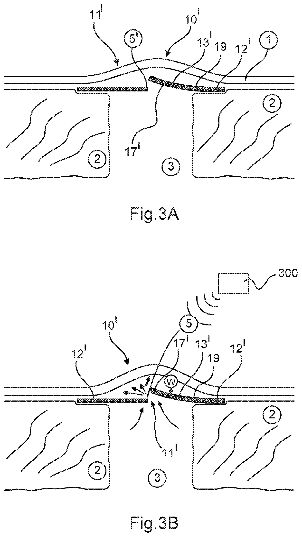
[0013]In one preferred variant, the pressure relief flap of the glaucoma drainage implant has an actuation area which is provided in the form of a thermomechanically active area. A shape-memory alloy may be advantageously used for this purpose. This has safety advantages, in particular. The pressure relief flap can thus be activated and opened by inputting heat.
[0015]It has been found to be advantageous when the thermomechanically active area is embodied as a shape-memory alloy. The thermomechanically active area, in particular, a thermomechanical area embodied as a metal plate, can be fully enclosed in the pressure relief flap. The thermoelastic area may include nitinol, for example, or a metal alloy. The thermomechanically active area in the form of a shape-memory material may be advantageously enclosed in the pressure relief flap.
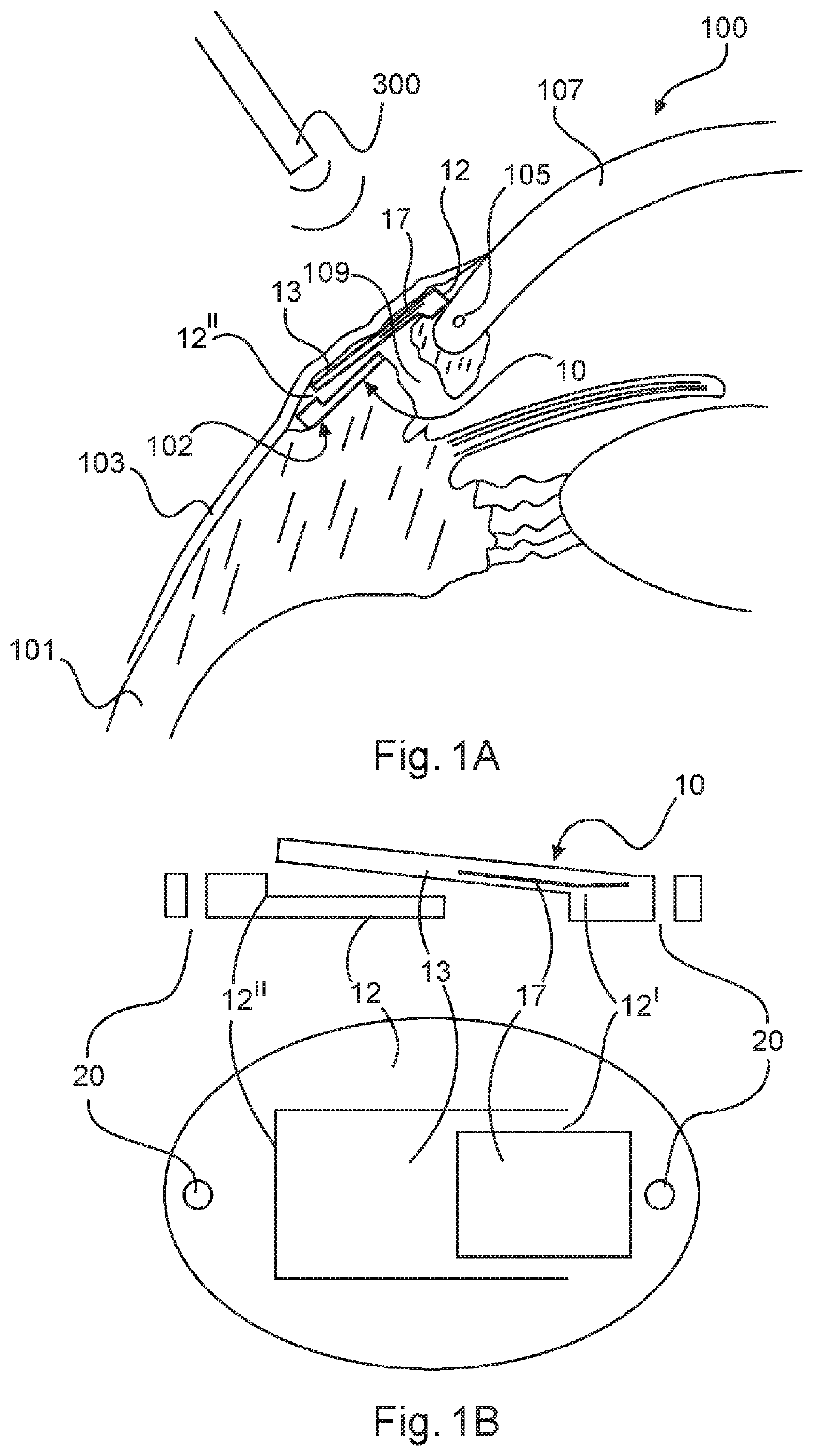
[0016]It has been found to be advantageous when the implant is disk-shaped. The implant preferably has a thickness of at most 0.8 mm and / or a width or diameter of at most 6 mm. This allows the implant to be placed near the corneal limbus or Schlemm's canal, and a complex drainage line to be dispensed with.
[0017]In another preferred variant, the pressure relief flap is movably connected with the base plate via a flexure joint. This allows a particularly compact and low-maintenance design of the implant. The pressure relief flap and the base plate may be integral with each other.
[0018]It has been found to be particularly advantageous when the base plate is step-shaped. Such a step-shaped base plate, in which the steps in the base plate are formed in a radial direction of the eye, helps to prevent sticking of the conjunctiva or Tenon's capsule and the pressure relief flap.
[0019]In another preferred variant, the pressure relief flap is framed by the base plate. The base plate is preferably annular in shape, with the pressure relief flap being circular in shape. Alternatively, the base plate may be designed in the shape of a frame. In this case, the pressure relief flap has an outer shape that is rectangular or square.
[0015]It has been found to be advantageous when the thermomechanically active area is embodied as a shape-memory alloy. The thermomechanically active area, in particular, a thermomechanical area embodied as a metal plate, can be fully enclosed in the pressure relief flap. The thermoelastic area may include nitinol, for example, or a metal alloy. The thermomechanically active area in the form of a shape-memory material may be advantageously enclosed in the pressure relief flap.
[0021]It has been found to be advantageous when the pressure relief flap has surface structuring on the side facing the cornea. In principle, however, the surface structuring may also be provided on the side facing away from the cornea, or on both sides.
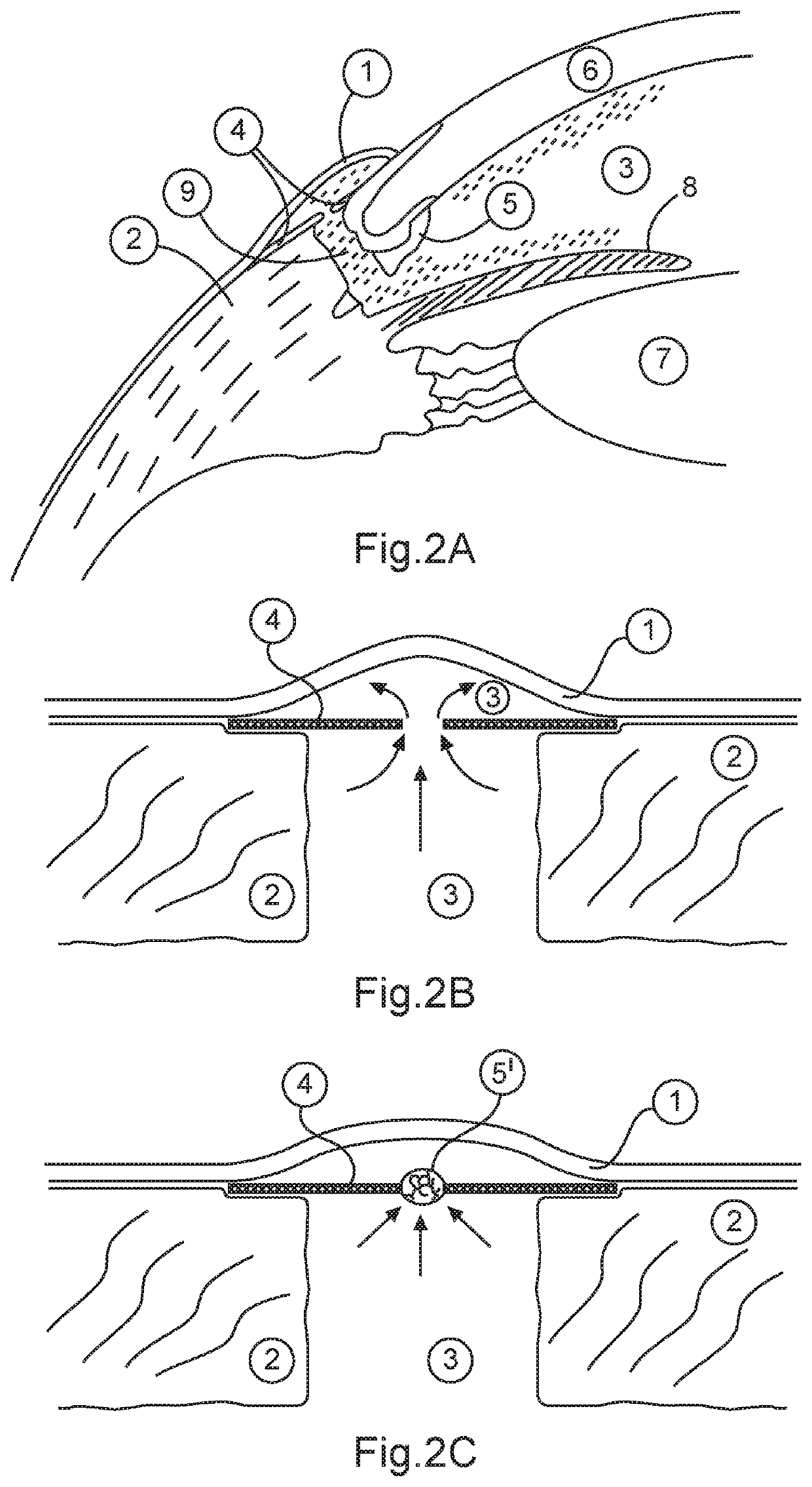
[0022]In one particularly preferred variant, the pressure relief valve is designed not to drain aqueous humor until the intraocular pressure exceeds 15 mmHg (about 20 mBar). In other words, the pressure relief valve is designed to regulate the intraocular pressure.
[0023]The object of the invention is likewise achieved by a method of implanting a glaucoma drainage implant into a human or animal eye, the method comprising the steps of creating a scleral bed in a sclera of the eye, said scleral bed having a drainage channel; implanting a glaucoma drainage implant as described in the foregoing into the scleral bed in such a way that the base plate closes the scleral bed water-tightly; and mobilizing the pressure relief flap, during or after a post-operative healing phase for the implant, by means of an energy source which generates a temperature gradient.
[0026]In one preferred variant of the method, heat is supplied (to produce a temperature increase in the thermomechanically active area) by irradiating with light, preferably infrared light, which is not absorbed by the surrounding tissue or only to a minor extent. Absorption of radiation by the material of the implant or part of the implant results in the increase in temperature. The thermal effect may be concentrated locally in a desired manner, by providing coloring which strongly absorbs the wavelengths being used, in the regions of the implant which are to heat up.
[0024]The method can be designed appropriately and advantageously by incorporating the features of the glaucoma drainage implant described above.
[0025]For example, the pressure relief flap of the glaucoma drainage implant used in the method may have an actuation area in the form of a thermomechanically active area.
[0026]In one preferred variant of the method, heat is supplied (to produce a temperature increase in the thermomechanically active area) by irradiating with light, preferably infrared light, which is not absorbed by the surrounding tissue or only to a minor extent. Absorption of radiation by the material of the implant or part of the implant results in the increase in temperature. The thermal effect may be concentrated locally in a desired manner, by providing coloring which strongly absorbs the wavelengths being used, in the regions of the implant which are to heat up.
[0027]Alternatively, or additionally thereto, a temperature increase can also be achieved inductively or by applying an electric current. In this case, the shape-memory material is designed to be electrically conductive, such that an eddy current which causes heating can be induced in the material by exposing it to an externally applied, high-frequency magnetic field. A pole shoe may be deployed and appropriately disposed in order to concentrate the field lines.

