
Portable cutting device

a cutting device and portable technology, applied in the direction of metal sawing devices, power-driven tools, manufacturing tools, etc., can solve the problems of difficult cutting tasks, difficult to provide a compact base, and limited configuration of the display portion, so as to reduce the number of components of the portable cutting device, the effect of reducing the size of the surrounding electric motor and easy and simple manner

Active Publication Date: 2021-02-09
MAKITA CORP
View PDF32 Cites 1 Cited by
  • Summary
  • Abstract
  • Description
  • Claims
  • Application Information

AI Technical Summary

Benefits of technology

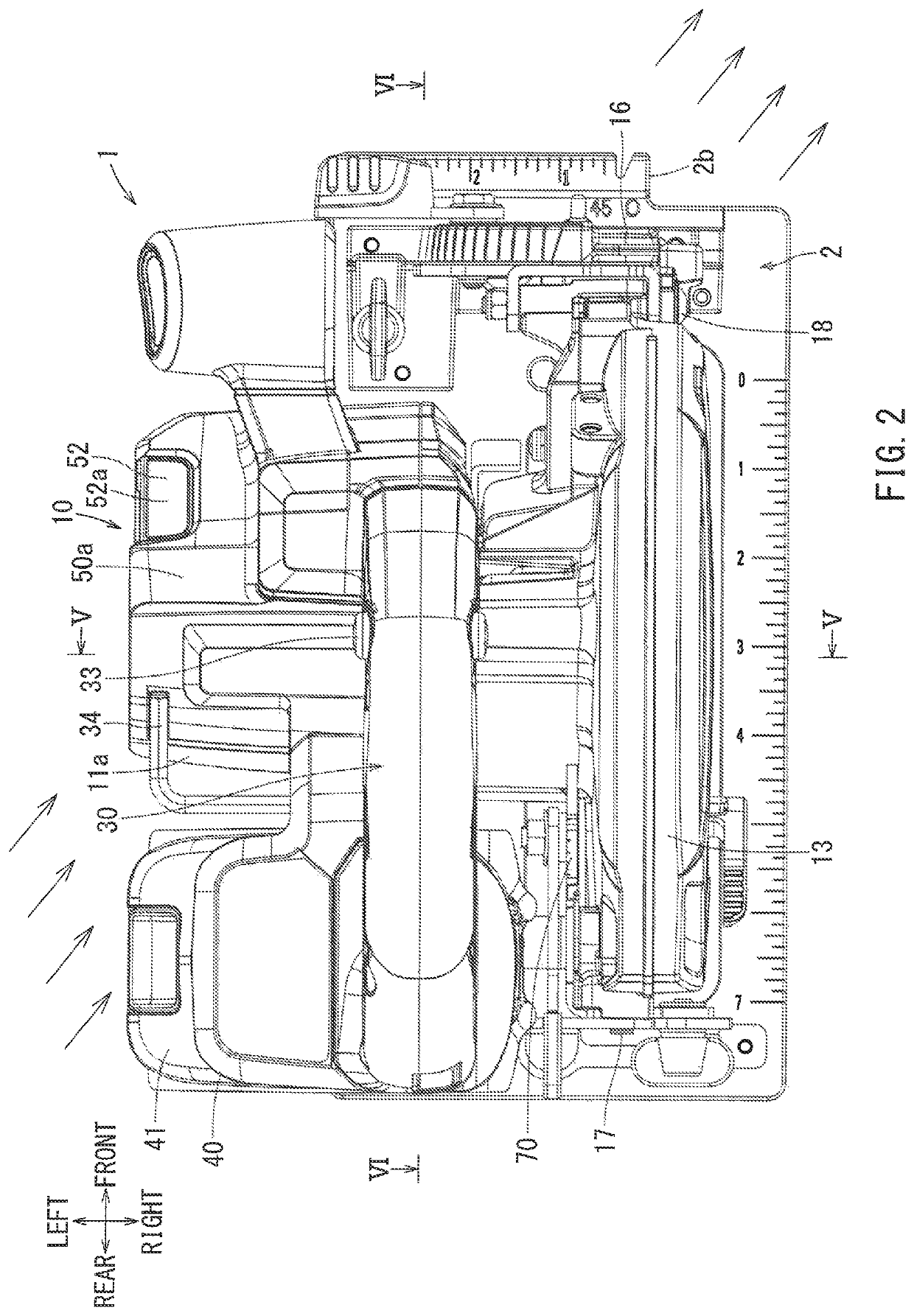
This configuration enables easier and more straightforward operation by ensuring the user can confirm the overlap between the saw blade and marking line without obstructing the view with the controller or display, while also minimizing the device's overall length and dimensions.

Problems solved by technology

Because of this requirement, it may not be easy to provide a compact base.
As a consequence, when the dimensions of the cutting device main body are to be minimized, the allocation of the display portion may be forced into a limited configuration due to lack of space.
In this situation, the user may find it difficult to perform the cutting task while viewing the display portion disposed behind the electric motor.

Method used


Image

  • Portable cutting device
  • Portable cutting device
  • Portable cutting device

Examples


Embodiment Construction

[0027]The detailed description set forth below, when considered with the appended drawings, is intended to be a description of exemplary embodiments of the present invention and is not intended to be restrictive and / or to represent the only embodiments in which the present invention can be practiced. The term “exemplary” used throughout this description means “serving as an example, instance, or illustration,” and should not necessarily be construed as preferred or advantageous over other exemplary embodiments. The detailed description includes specific details for the purpose of providing a thorough understanding of the exemplary embodiments of the invention. It will be apparent to those skilled in the art that the exemplary embodiments of the invention may be practiced without these specific details. In some instances, these specific details refer to well-known structures, components and / or devices that are shown in block diagram form in order to avoid obscuring significant aspect...


PUM

PropertyMeasurementUnit
angleaaaaaaaaaa
tilt angleaaaaaaaaaa
electric poweraaaaaaaaaa

Abstract

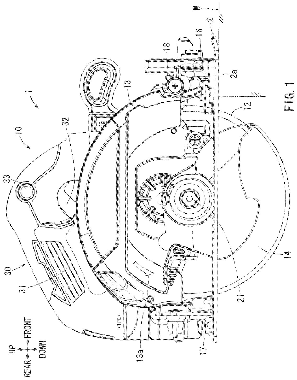
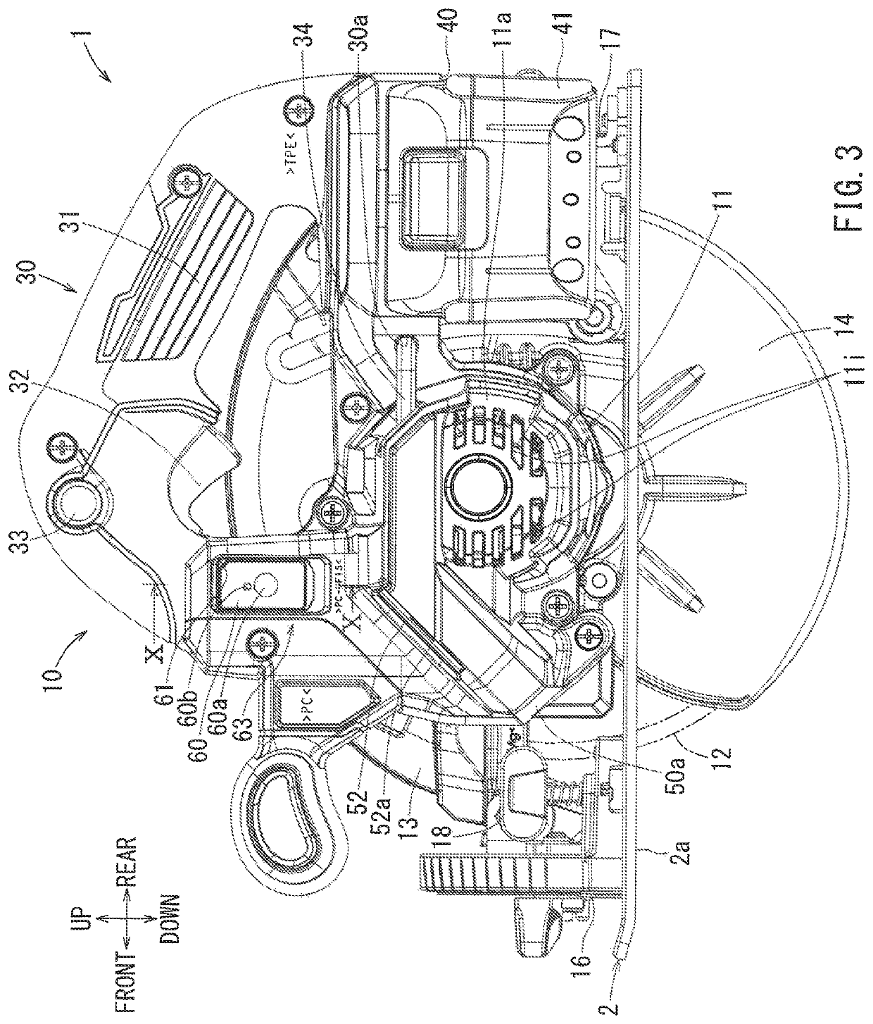
A controller 50 is disposed to the front relative to a rotation shaft 11d of an electric motor 11 above a base 2, so as to be tilted in the up-to-down direction as it extends frontward.

Description

CROSS-REFERENCE[0001]This application claims priority to Japanese patent application serial number 2017-218817, filed on Nov. 14, 2017, the contents of which are incorporated herein by reference in their entirety.TECHNICAL FIELD[0002]The present invention generally relates to a portable cutting device that is operated by a user while holding the device, such as, for example, a portable circular saw or a portable jig saw.BACKGROUND ART[0003]Various portable circular saws are disclosed in, for example, Japanese Laid-Open Patent Publication No. 2015-112652 (hereinafter referred to as “patent document 1”), Japanese Laid-Open Patent Publication No. 2014-79873 (hereinafter referred to as “patent document 2”), Japanese Laid-Open Patent Publication No. 2015-178226 (hereinafter referred to as “patent document 3”), and Japanese Laid-Open Patent Publication No. 2013-193133 (hereinafter referred to as “patent document 4”). Generally, the disclosed portable circular saws in the above documents c...

Claims


Application Information

Patent Timeline
Patent Type & Authority Patents(United States)
IPC IPC(8): B23D45/16B27B9/02B23D47/12B25F5/02B26B25/00B23Q11/06
CPCB27B9/02B23D45/16B23D47/12B23Q11/06B25F5/02B26B25/00
Inventor NAKASHIMA, TATSUO
Owner MAKITA CORP
Learn More