
Method of pre-controlling shapes of continuous-casting slab head and tail for reducing head and tail cut amount of hot rolling intermediate slab

a technology of continuous casting and shape control, applied in the direction of metal rolling, metal rolling arrangement, manufacturing tools, etc., can solve the problems of unfavorable scalding of continuous casting slabs, meaningless temperature drop, and inability to stably roll tails, so as to reduce the cut amount of head and tail, reduce the length of uneven deformation parts, and reduce the effect of head and tail cut amoun

Active Publication Date: 2018-03-13
BAOSHAN IRON & STEEL CO LTD
View PDF14 Cites 0 Cited by
  • Summary
  • Abstract
  • Description
  • Claims
  • Application Information

AI Technical Summary

Benefits of technology

This approach reduces the cut length of heads and tails by 13.3%, decreasing yield loss and improving production efficiency, while maintaining material yield in the continuous casting region and offering energy conservation benefits.

Problems solved by technology

If processing times in a device is an even number, there must be one dummy pass, which may result in a meaningless temperature drop.
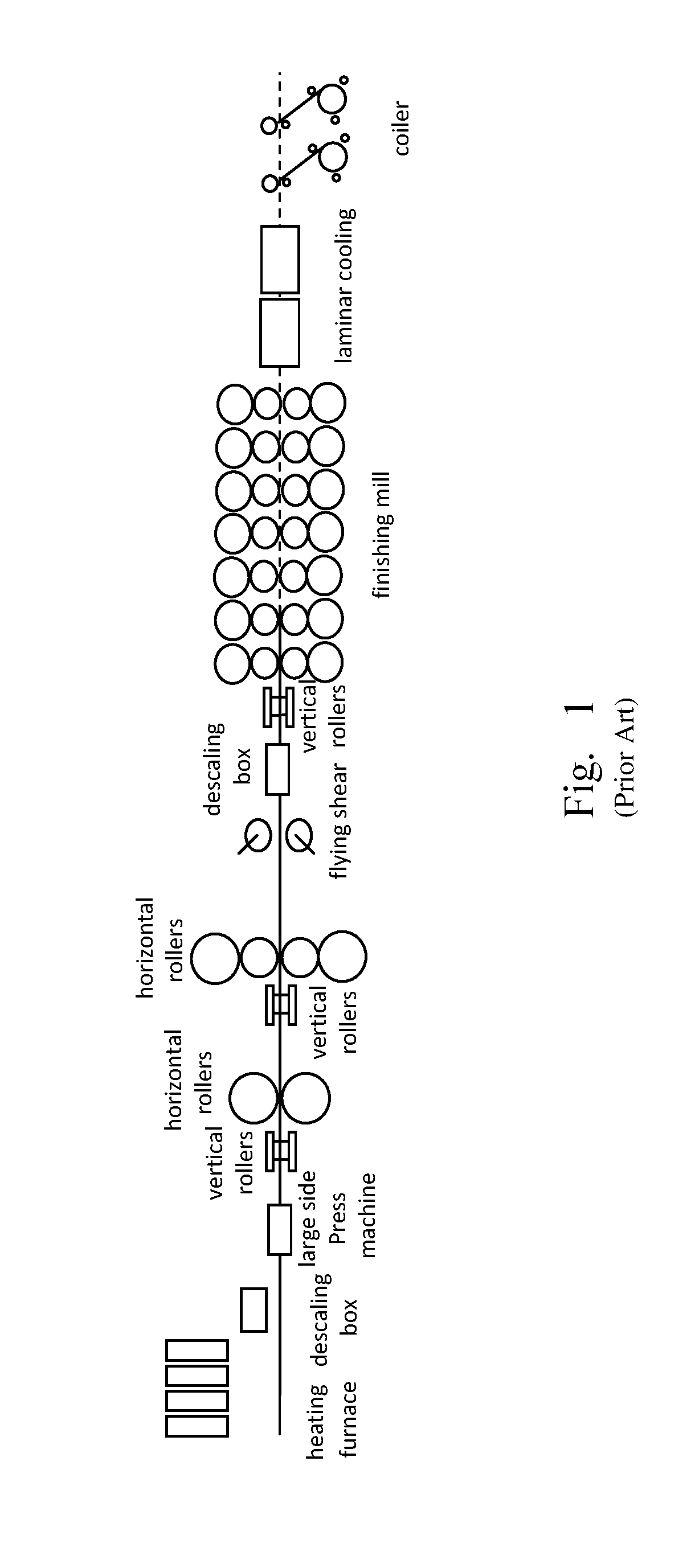
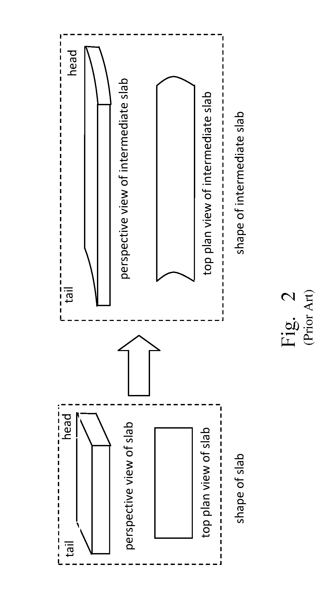
The irregular shapes of the head and the tail of the intermediate slab after rough rolling may cause accidents when the material enters into the finishing mill, for instance, the head cannot pass through rollers smoothly, or the tail cannot be rolled stably.
In view of this, a set of flying shear is provided between the rough mill and the finishing mill to cut away the irregular parts of the head and tail of the intermediate slab, which may cause the yield loss during production, affecting the production efficiency of the hot rolling line.
Empirically, the loss for cutting the head and tail of the intermediate slab accounts for about 30% of the hot rolling yield loss.
But even if a variety of methods have been used, the yield loss resulted from the bad head and tail shapes of the intermediate slab is still a main problem.

Method used


Image

  • Method of pre-controlling shapes of continuous-casting slab head and tail for reducing head and tail cut amount of hot rolling intermediate slab
  • Method of pre-controlling shapes of continuous-casting slab head and tail for reducing head and tail cut amount of hot rolling intermediate slab
  • Method of pre-controlling shapes of continuous-casting slab head and tail for reducing head and tail cut amount of hot rolling intermediate slab

Examples


embodiments

[0049]To testify the effect of the method of pre-controlling the slab head and tail shapes, a cutting and rolling test is done in the hot rolling line. In the test, the way of pre-controlling the slab head and tail shapes, the head and tail cut amount of the intermediate slab after rolling and the effect for reducing the cut amount is described.

[0050]The conditions of the slab: to testify the effect of pre-controlling the shapes of the slab head and tail under different arc heights, four groups of tests are designed. In each group of test, two slabs with the identical thickness and width is selected, one of which is used for the head and tail pre-control process (the arc at the head assumes concaving and that at the tail assumes projecting), and another is a conventional cuboid slab for comparison. Eight slabs are selected, the relative data of which is shown in the tables 1-1 to 1-4.

[0051]

TABLE 1-1The First Group Of Test Slabs (Unit: mm)HeadTailTargetTargetPrecontrolArcArcSlabSlabS...


PUM

PropertyMeasurementUnit
lengthaaaaaaaaaa
lengthaaaaaaaaaa
lengthaaaaaaaaaa

Abstract

A method of pre-controlling the shapes of a continuous-casting slab head and tail for reducing the cut amount of the head and tail of the hot rolling intermediate slab. The continuous-casting slab head and tail, is cut into a shape such that an end surface of the head concaves inwards and the tail projects outwards. The head and tail of a slab is cut in a curve that is symmetric to the center line in width thereof. Arc height, i.e. a maximum value of the concave amount at the head or that of the projection amount at the tail, is controlled within 0 mm-50 mm.

Description

[0001]This application is a U.S. National Phase of International Application No. PCT / CN2012 / 072299, filed Mar. 14, 2012, which claims priority to the Chinese Patent Application No. 201210038624.3, filed Feb. 21, 2012, the disclosures of which are incorporated by reference herein.FIELD OF THE INVENTION[0002]The present invention relates to a method of pre-controlling the shapes of continuous-casting slab head and tail.BACKGROUND OF THE INVENTION[0003]With the continued improvement of the continuous casting—hot rolling process, hot rolling slabs are changed from original blooms to continuous-casting slabs. Usually, over 90% of hot rolling slabs come from the continuous casting.[0004]During continuous casting, molten steel is poured, solidified and cut, and after this, the cut continuous-casting slab is sent into the hot rolling line to be rolled. Currently, the method of cutting a continuous-casting slab into cuboids is used internationally.[0005]A conventional hot continuous rolling ...

Claims


Application Information

Patent Timeline
Patent Type & Authority Patents(United States)
IPC IPC(8): B22D11/126B22D11/16B21B1/46B21B15/00
CPCB22D11/126B22D11/163Y10T83/04B21B2015/0014B21B1/466B21B1/46B21B15/00
Inventor SHAN, XUYIZHANG, SUOQUANHUANG, LIDING, HONGRUWANG, ZIQIANGZHU, WEILINWANG, QUANSHENG
Owner BAOSHAN IRON & STEEL CO LTD
Learn More