

Method and system for tubing a borehole in single diameter
- Summary
- Abstract
- Description
- Claims
- Application Information
AI Technical Summary
Benefits of technology
Problems solved by technology
Method used
Image

Examples
second embodiment
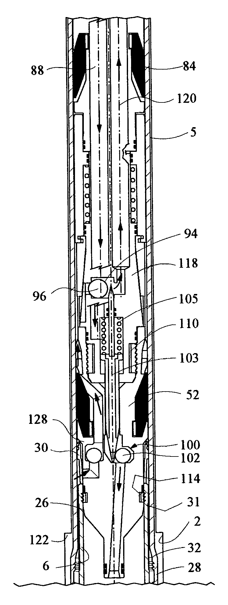
[0049] Once unscrewed, the operator applies internal fluid pressure to drill pipe 54. The pressure flows through passage 88 and out the lower end of lower body 118. This pressure enters port 140 driving down actuating sleeve 142 which push slips 150 over the conical profile of tool body 118 against the inner wall of installed casing string 5 to prevent running tool 50 to move upward. Helicoidal spring 148 prevented the locking of slips 150 during lowering of casing 6 through casing 5. This pressure acts also against the cup tester 89 of detachable gauge 52, forcing it downward. Drifting elements 128 will round out casing string 6 to the desired configuration as detachable gauge 52 moves downward in lower casing string 6. At the lower end of casing string 6, detachable gauge 52 will enter cement shoe 34, as shown in FIG. 9 for the The lower concentric end of detachable gauge 52 enters a receptacle in cement shoe 34 directly above ball 39. Then the operator stops pumping fluid throug...
first embodiment
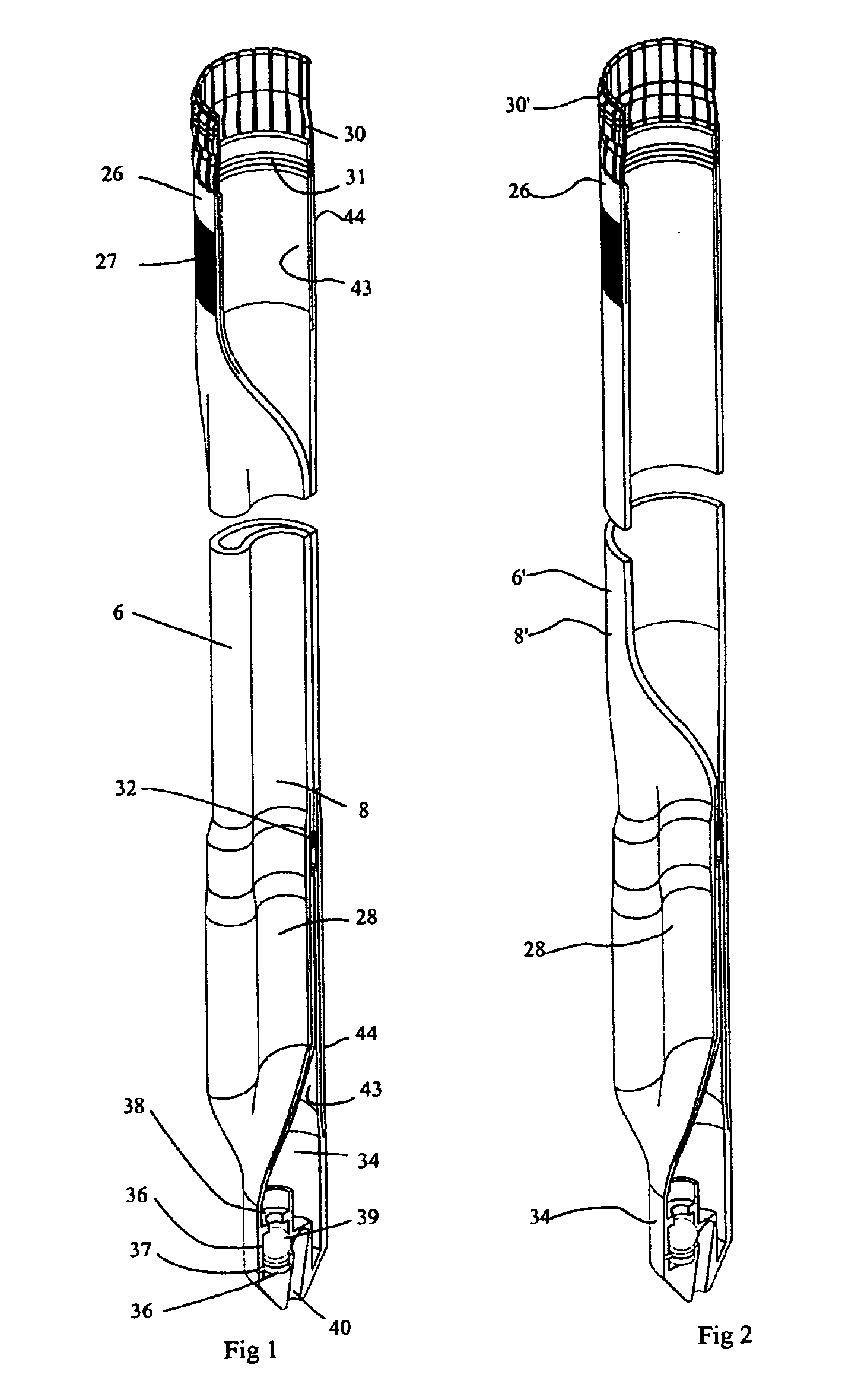
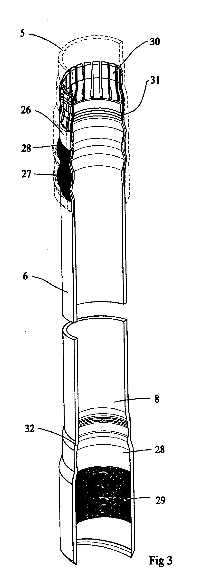
[0056] As illustrated in FIG. 6a, collet fingers 30 of the top hanger 26 will snap into grooved profile 32 of the bottom bell 28 of the previously installed string 5′. The operator applies pressure to drill pipe 54 which causes bottom bell 28 of string 6′ to inflate as shown in FIG. 6b. The fluid pressure transmits through running tool 50 in the same manner as the Running tool 50 is then pushed down a short distance to the position shown in FIG. 7b, with expanding elements 128′, and a lower expanding element 130′ with a smaller outside diameter than the upper drifting element 128′ located within casing string 6′. By locating two or more expanding elements having different expanding diameters, we prevent early striction to occur on the expanding cone triggered by small defects. This downward movement occurs by applying pressure to the drill pipe annulus 58 (FIG. 6a), which acts against lower cup tester 82 to push the entire assembly downward. As drift elements 128, 130 entered lower...
PUM
 Abstract
Description
Claims
Application Information