
Thick plate welding stirring head and thick plate welding equipment

The technology of stirring head and stirring needle is applied in the field of thick plate welding stirring head and thick plate welding equipment, which can solve problems such as internal defects of workpieces and achieve the effect of reducing cutting volume.

Pending Publication Date: 2022-03-25
北京碳垣智能科技发展有限公司
View PDF6 Cites 0 Cited by
  • Summary
  • Abstract
  • Description
  • Claims
  • Application Information

AI Technical Summary

Problems solved by technology

[0005] The purpose of the present invention is to provide a thick plate welding stirring head and thick plate welding equipment to solve the problem of internal defects of the workpiece caused by the friction stirring head when welding medium and thick plates in the prior art

Method used


Image

  • Thick plate welding stirring head and thick plate welding equipment
  • Thick plate welding stirring head and thick plate welding equipment
  • Thick plate welding stirring head and thick plate welding equipment

Examples


Embodiment Construction

[0023] The technical solutions of the present invention will be clearly and completely described below in conjunction with the accompanying drawings. Apparently, the described embodiments are some of the embodiments of the present invention, but not all of them. Based on the embodiments of the present invention, all other embodiments obtained by persons of ordinary skill in the art without making creative efforts belong to the protection scope of the present invention.

[0024] In the description of the present invention, it should be noted that the terms "center", "upper", "lower", "left", "right", "vertical", "horizontal", "inner", "outer" etc. The indicated orientation or positional relationship is based on the orientation or positional relationship shown in the drawings, and is only for the convenience of describing the present invention and simplifying the description, rather than indicating or implying that the referred device or element must have a specific orientation, ...


PUM


Abstract

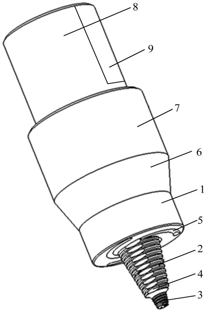
The invention belongs to the technical field of friction stir welding, and particularly relates to a thick plate welding stirring head and thick plate welding equipment, and the thick plate welding stirring head comprises a shaft shoulder and a stirring part; the stirring part comprises a first stirring needle and a second stirring needle; the first stirring needle is connected between the shaft shoulder and the second stirring needle, and the first stirring needle, the shaft shoulder and the second stirring needle are coaxially arranged; the needle length and the diameter of the second stirring needle are smaller than those of the first stirring needle, and the connection position of the first stirring needle and the second stirring needle is in step surface transition. By means of the structure, the problem of S lines generated during thick plate welding can be solved, and meanwhile welding defects are reduced.

Description

technical field [0001] The invention belongs to the technical field of friction stir welding, and in particular relates to a thick plate welding stirring head and thick plate welding equipment. Background technique [0002] Friction stir welding refers to the use of heat generated by the friction between the high-speed rotating welding tool and the workpiece to locally melt the material of the welded workpiece. When the welding tool moves forward along the welding section, the plasticized material is under the action of the rotating friction of the welding tool It flows from the front of the welding tool to the rear, and forms a dense solid-phase weld under the extrusion of the welding tool. [0003] The stirring head used for friction stir welding mainly includes a shoulder and a stirring pin, wherein the shoulder is used to provide welding heat source through friction with the surface of the workpiece, and the stirring pin is used to provide heat input through friction wit...

Claims


Application Information

Patent Timeline
Patent Type & Authority Applications(China)
IPC IPC(8): B23K20/12
CPCB23K20/1255
Inventor 侯红亮王卫兵赵大龙赵晓
Owner 北京碳垣智能科技发展有限公司
Learn More