Shift device

a technology of shift device and shift knob, which is applied in the direction of mechanical control device, machine control, instruments, etc., can solve the problems of annoyance of drivers, different operation positions of the shift knob, and rotation of the knob generating driving noise, so as to reduce the speed of the detent pin moving and less annoy the driver

Active Publication Date: 2021-02-09
KK TOKAI RIKA DENKI SEISAKUSHO
View PDF10 Cites 1 Cited by
  • Summary
  • Abstract
  • Description
  • Claims
  • Application Information

AI Technical Summary

Benefits of technology

[0006]It is an object of the present invention to provide a shift device that is less annoying to the driver when returning the knob to a predetermined operation position.
[0008]In the above structure, if particular conditions are satisfied, the controller controls the drive source to rotate the knob to the operation position corresponding to a predetermined gear mode. In this case, during a period in which the cam member is rotated in at least until the cam member engages the portion of the knob, the controller decreases the voltage applied to the drive source from that when the cam member is rotated in other sections. Thus, the speed is reduced until the cam member engages the portion of the knob. This reduces the striking noise generated when the cam member engages the portion of the knob. This will less annoy the driver when the knob returns to a predetermined shift position, for example, the parking position.
[0014]In the above structure, the controller determines that the cam member has engaged the portion of the knob when the current value of the drive source becomes greater than or equal to the predetermined value. This allows the controller to determine that the cam member has engaged the portion of the knob from the actual engagement result without a detector that detects rotation of the cam member.
[0018]The above structure decreases the speed of the detent pins moving from the peak of each ridge on the detent surface toward the adjacent valley. Thus, the striking noise generated when the detent pins strike the vicinity of the bottoms of the valleys in the detent surface is reduced. Further, the controller determines the period until the detent pins move from the vicinity of the peaks of the ridges on the detent surface to the bottoms of the valleys based on the predetermined time from when the rotation starts. This allows the controller to determine the positions of the detent pins relative to the detent surface without a detector that detects rotation of the cam member.

Problems solved by technology

This results in the operation position of the knob of the shift differing from the gear mode of the transmission.
When the knob is returned to the parking position in such a manner, the rotation of the knob generates a driving noise in a state in which the engine is stopped.
This may be annoying to the driver.

Method used


Image

  • Shift device
  • Shift device
  • Shift device

Examples


Embodiment Construction

[0033]One embodiment of a shift device will now be described with reference to FIGS. 1 to 12.

[0034]Mechanical Structure

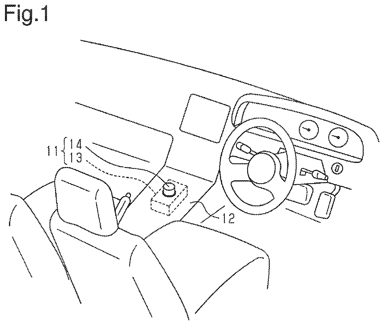
[0035]As illustrated in FIG. 1, a shift device 11 is provided on a center console 12 of a vehicle. The shift device 11 includes a case 13 and a cylindrical dial knob 14 arranged to be rotatable relative to the case 13. The case 13 is arranged in the center console 12. The dial knob 14 is exposed to the outside of the center console 12. The dial knob 14 is rotated to shift gear modes of a transmission (not illustrated).

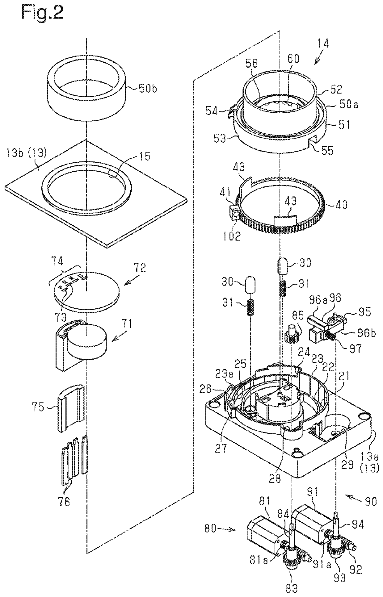
[0036]As illustrated in FIG. 2, the case 13 includes a box-shaped case body 13a and a cover 13b that covers the upper part of the case body 13a. The cover 13b includes a hole 15 through which a dial knob 14 extends. The dial knob 14 includes a tubular knob body 50a and a tubular knob cover 50b attached to an upper circumferential surface of the knob body 50a.

[0037]An annular groove 21 is formed in the upper part of the case body 13a. The annular groov...


PUM


Abstract

A shift device includes a knob that is rotatable to select one of a plurality of gear modes of a transmission of a vehicle and a cam member that engages a portion of the knob in a rotation direction of the knob. The cam member rotates integrally with the knob only when engaged with the portion of the knob. The shift device further includes a drive source that rotates the cam member and a controller. The controller controls the drive source to rotate the knob to an operation position corresponding to a predetermined gear mode if a particular condition is satisfied. The controller decreases a voltage applied to the drive source when the cam member is rotated in at least a pre-engagement section until the cam member engages the portion of the knob from the voltage applied when the cam member is rotated in other sections.

Description

TECHNICAL FIELD[0001]The present invention relates to a shift device that shifts gear modes of a transmission by performing a rotation operation.BACKGROUND ART[0002]In shift devices, a by-wire shift device that shifts gear modes of a transmission by rotating a knob is being developed (refer to, for example, patent document 1).[0003]The shift device described in patent document 1 includes a detent mechanism that holds a knob at an operation position corresponding to a selected gear mode. The vehicle includes a controller that controls the gear mode of the transmission in accordance with the operation position of the knob of the shift device.[0004]Patent Document 1: Japanese Laid-Open Patent Publication No. 2015-107671SUMMARY OF THE INVENTION[0005]In the by-wire shift device, the driver may stop the engine without shifting the operation position of the knob of the shift device to the parking position. In such a case, the controller performs an automatic return control that shifts the ...

Claims


Application Information

Patent Timeline
Patent Type & Authority Patents(United States)
IPC IPC(8): F16H59/08F16H61/18F16H61/28F16H63/34F16H63/40G05G1/08
CPCF16H59/08F16H61/18F16H61/28F16H63/34F16H63/40G05G1/08F16H2059/081B60K20/02F16H61/24F16H2061/243F16H2061/326G05G1/10
Inventor YAMAMOTO, MAKOTOKATAGIRI, TOSHIHARUOGATA, SHUJI
Owner KK TOKAI RIKA DENKI SEISAKUSHO
Why Eureka
Try Eureka