
Orthodontic bracket with sliding molar distalizer

a technology of sliding molars and brackets, which is applied in the direction of brackets, arch wires, etc., can solve the problems cumbersome external headgear wear, and difficult assembly, so as to reduce the effect of catching on the inside of the patient's cheek

Active Publication Date: 2021-03-09
SPARTAN ORTHODONTICS INC
View PDF7 Cites 2 Cited by
  • Summary
  • Abstract
  • Description
  • Claims
  • Application Information

AI Technical Summary

Benefits of technology

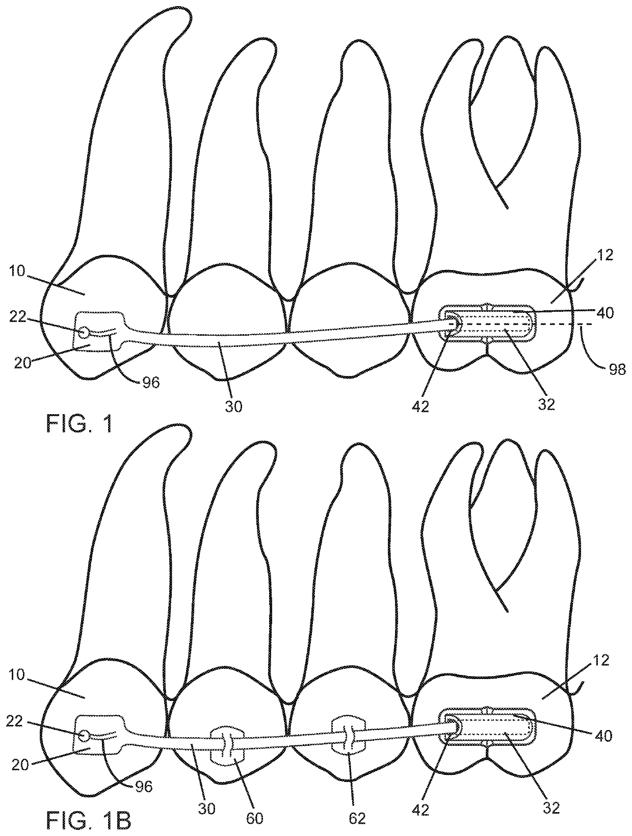
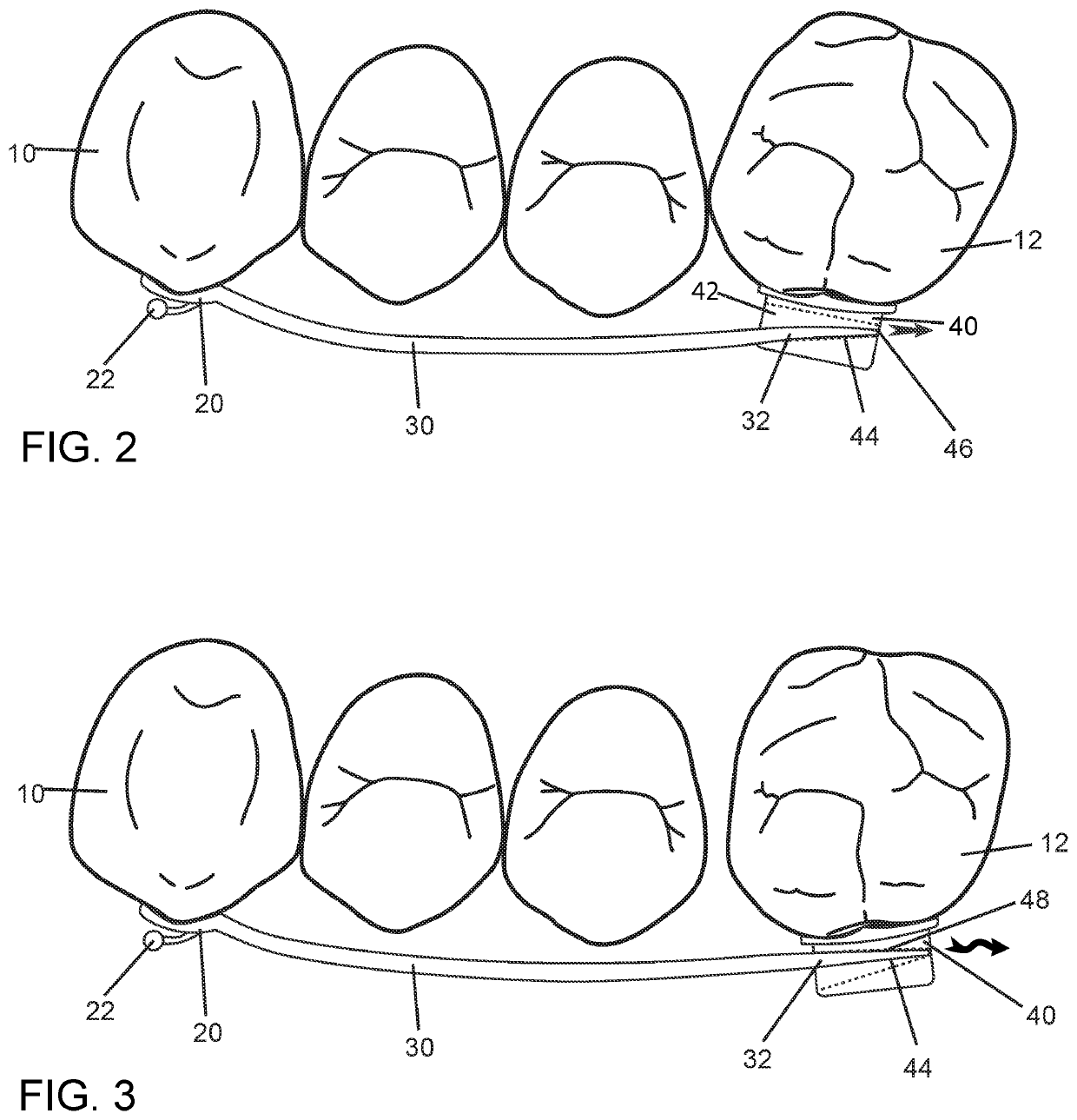
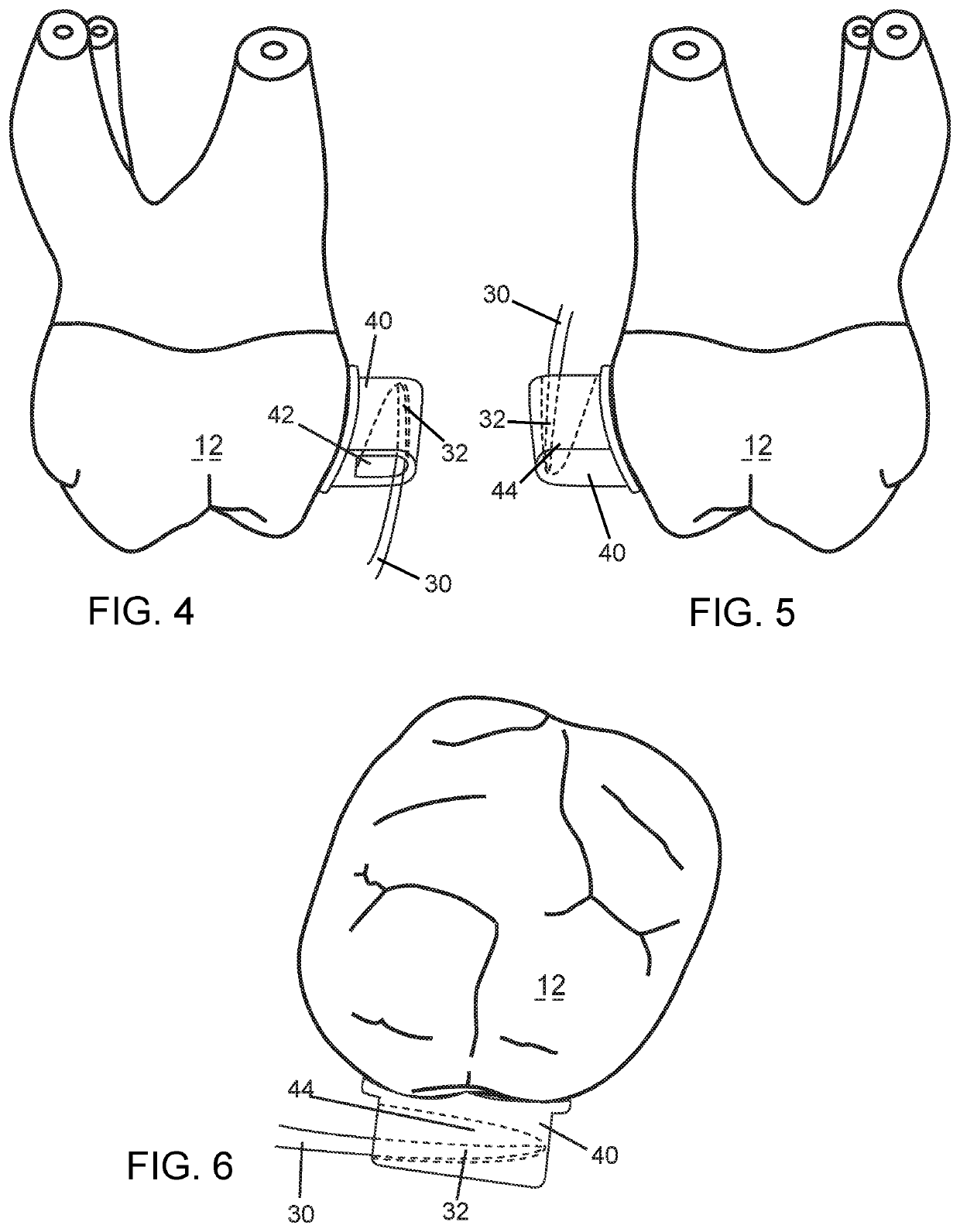
The orthodontic appliance described in this patent has a curved rod with a hook at the end that attaches to a molar tube. The hook is designed to be smooth to prevent catching in the patient's cheek. The curved rod also has a blocking feature to prevent it from being removed from the molar tube. The appliance has an archwire slot for allowing an archwire to pass through it. A buccal flange lever is attached to the curved rod to engage the molar tube when the curved rod is moved by a traction elastic. The technical effects of this design include improved orthodontic treatment and greater comfort for the patient.

Problems solved by technology

This is often referred to as a skeletal dysplasia characterized by overjet of the upper jaw and upper incisors, and often requires cumbersome external headgear wear.
These distalizer mechanisms as described above are often complex and difficult to manufacture in three or four pieces with additional precision rotation pins through the rod connecting intricately to the distal component, and difficult to assemble.
The projecting pivot and slot that limits rotation also increases difficulty in assembly.
As two distalizers are used for balance in total, one on the left side and one on the right side of the upper jaw, a complex distalizer is cost prohibitive.
These lateral pins result in the force on the mesial segment being applied, and being limited by the slot on the disk-shaped, located specifically on the lateral lingual surface due to the coupling with the receptacle of the distal segment.
Furthermore, when a force is applied at the level of the molar crown, the crown of the tooth begins to tip posteriorly, which can later, after treatment in retention, result in the tipped molar crown re-aligning itself under the forward position of the root.
In addition, the other more visible and common complications is that the upper canines can over-erupt due to the elastic traction that poses an aesthetic issue for patients.

Method used


Image

  • Orthodontic bracket with sliding molar distalizer
  • Orthodontic bracket with sliding molar distalizer
  • Orthodontic bracket with sliding molar distalizer

Examples


Embodiment Construction

[0043]With reference to FIG. 1 to FIG. 6, a sliding distalizer is provided. The sliding distalizer comprises an angled rhomboid or rectangular-shaped attachment bracket 20 affixed to a canine tooth 10. The attachment bracket 20 has a ball hook 22, to attach a separate traction force elastic (not shown) to a lower molar at a diagonal in order to exert force on the attachment bracket 20. The ball hook 22 is smooth in order to reduce catching of the hook 22 on the inside of the patient's cheek. The attachment bracket 20 may be integrally formed at, or attached to, a portion of a long rod 30 that extends towards the back of the mouth in a mesiodistal direction. The rod 30 is slightly curved in the buccal-lingual plane, but relatively straight in the gingival-occlusal plane. The rod 30 enters an upper molar tube 40, affixed to a molar tooth 12, via a wide opening 42 on a mesial side, more clearly shown in FIG. 4 to FIG. 6. The upper molar tube 40 may be shaped so that opening 42 is gener...


PUM


Abstract

A sliding molar distalizer is provided. The distalizer features a canine attachment bracket, a molar tube, and a rod connected to the bracket and having an engagement end for engaging the molar tube. A hook formed on a portion of the rod receives an elastic for imparting distalization force directly on the distalizer towards the molar tube. An orthodontic tube formed on the attachment bracket holds an archwire that passes through premolar brackets. A buccal push flange lever is formed at a distal portion of the rod for imparting force on the molar tube.

Description

RELATED APPLICATIONS[0001]This application claims priority from U.S. Provisional Patent Application No. 62 / 248,020 filed Oct. 29, 2015; the contents of which are herein expressly incorporated by reference.FIELD OF THE INVENTION[0002]The present invention relates to the field of orthodontic brackets, and more particularly to a sliding molar distalizer.BACKGROUND OF THE INVENTION[0003]A malocclusion is a misalignment or incorrect relation between the 2 jaws, maxilla and mandible, and the teeth of the respective two dental arches. This is often referred to as a skeletal dysplasia characterized by overjet of the upper jaw and upper incisors, and often requires cumbersome external headgear wear. There are generally three orthodontic terms to describe direction. Buccal-lingually means from the cheek side to the tongue side. Mesial-distally means from anterior to posterior or front to back. Occlusal-gingivally means from the bite side to the gum side. Malocclusion or malalignment of the bi...

Claims


Application Information

Patent Timeline
Patent Type & Authority Patents(United States)
IPC IPC(8): A61C7/28A61C7/22A61C7/12
CPCA61C7/282A61C7/12A61C7/22A61C7/28
Inventor VOUDOURIS, JOHN
Owner SPARTAN ORTHODONTICS INC
Learn More