
Display for incorporating in a pair of eyeglasses

a technology of optical imager and display, which is applied in the field of display comprising optical imager, can solve the problems of large amount of slack, prejudicious display accuracy, and rise to constraints in the way, and achieve the effect of prolonging the life of the display

Active Publication Date: 2015-08-11
ESSILOR INT CIE GEN DOPTIQUE
View PDF6 Cites 0 Cited by
  • Summary
  • Abstract
  • Description
  • Claims
  • Application Information

AI Technical Summary

Benefits of technology

The invention describes a way to connect a light beam generator system to a lens of information eyeglasses that solves the problems of severe mechanical, optical, size, weight, and appearance constraints. The design uses hooks that can be easily assembled with little force and are discreet on the lens. The hooks are designed to reduce the risk of catching on fabric or other objects. The connection arrangement is reliable and provides isostatic fastening without residual movement. Overall, the invention meets the needs of a wide range of users and offers a convenient and easy-to-use solution for connecting a light beam generator system to information eyeglasses.

Problems solved by technology

That connection and focus-adjusting device presents the following technical problems.
This can give rise to constraints in the way it is made.
That type of device inevitably leads to a large amount of slack between the rods and the slideways, which can be prejudicial to the accuracy of the display.
As a result the housing wears quickly, thereby further increasing slack and inaccuracy of the display.
Naturally, such an arrangement is not very accurate and not very comfortable to use, being ill-suited to everyday use of a non-experimental kind.
Although the number of parts used is thus minimized, it is nevertheless found that that connection arrangement does not give complete satisfaction, since its positioning and its movements for the purpose of snap-fastening the two arms on the hooks are relatively complex.
They also require the deformable tongue to be pushed so as to deform and as a result they require a force to be applied to the hooks, which are consequently rendered fragile.

Method used


Image

  • Display for incorporating in a pair of eyeglasses
  • Display for incorporating in a pair of eyeglasses
  • Display for incorporating in a pair of eyeglasses

Examples


Embodiment Construction

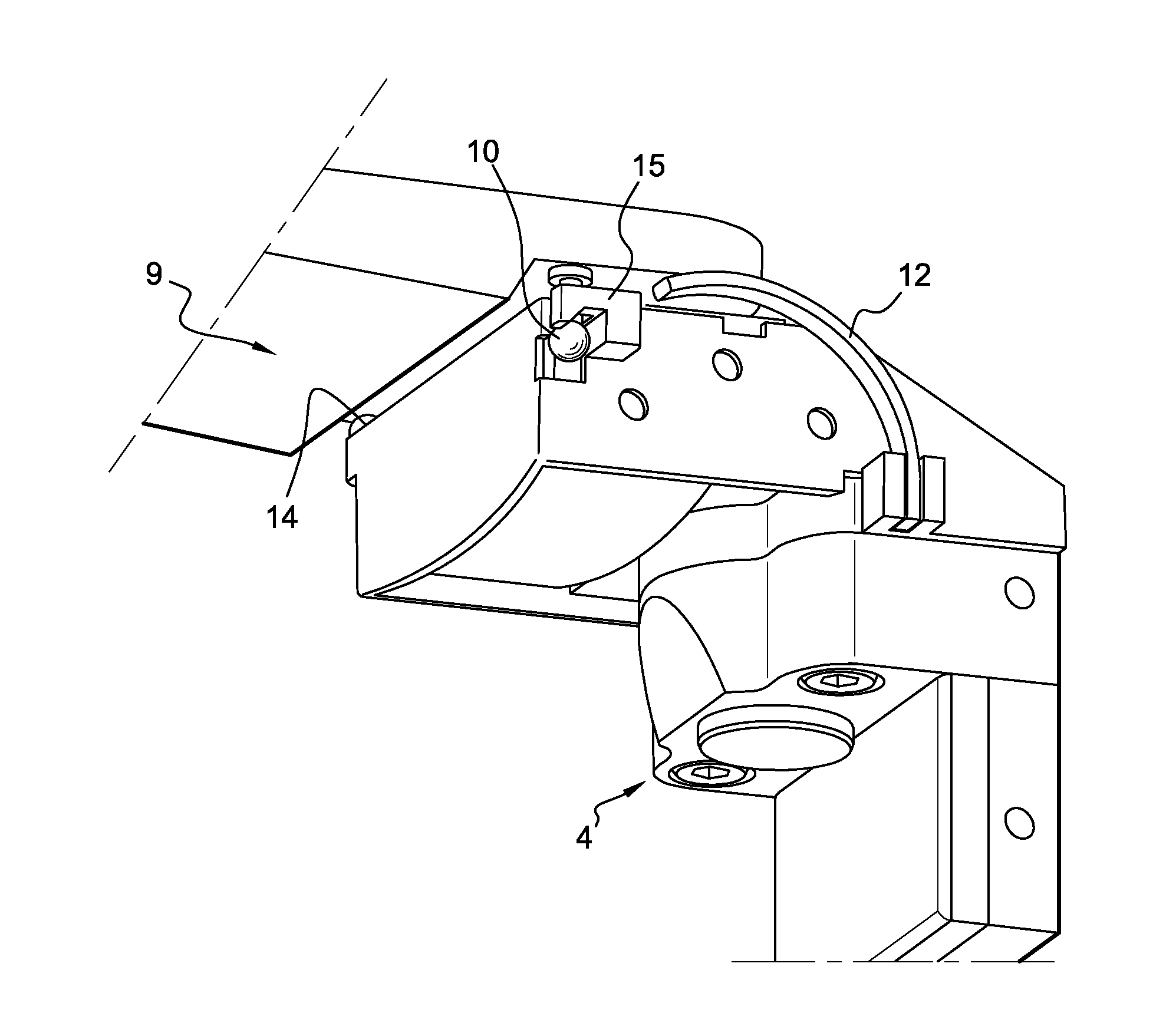
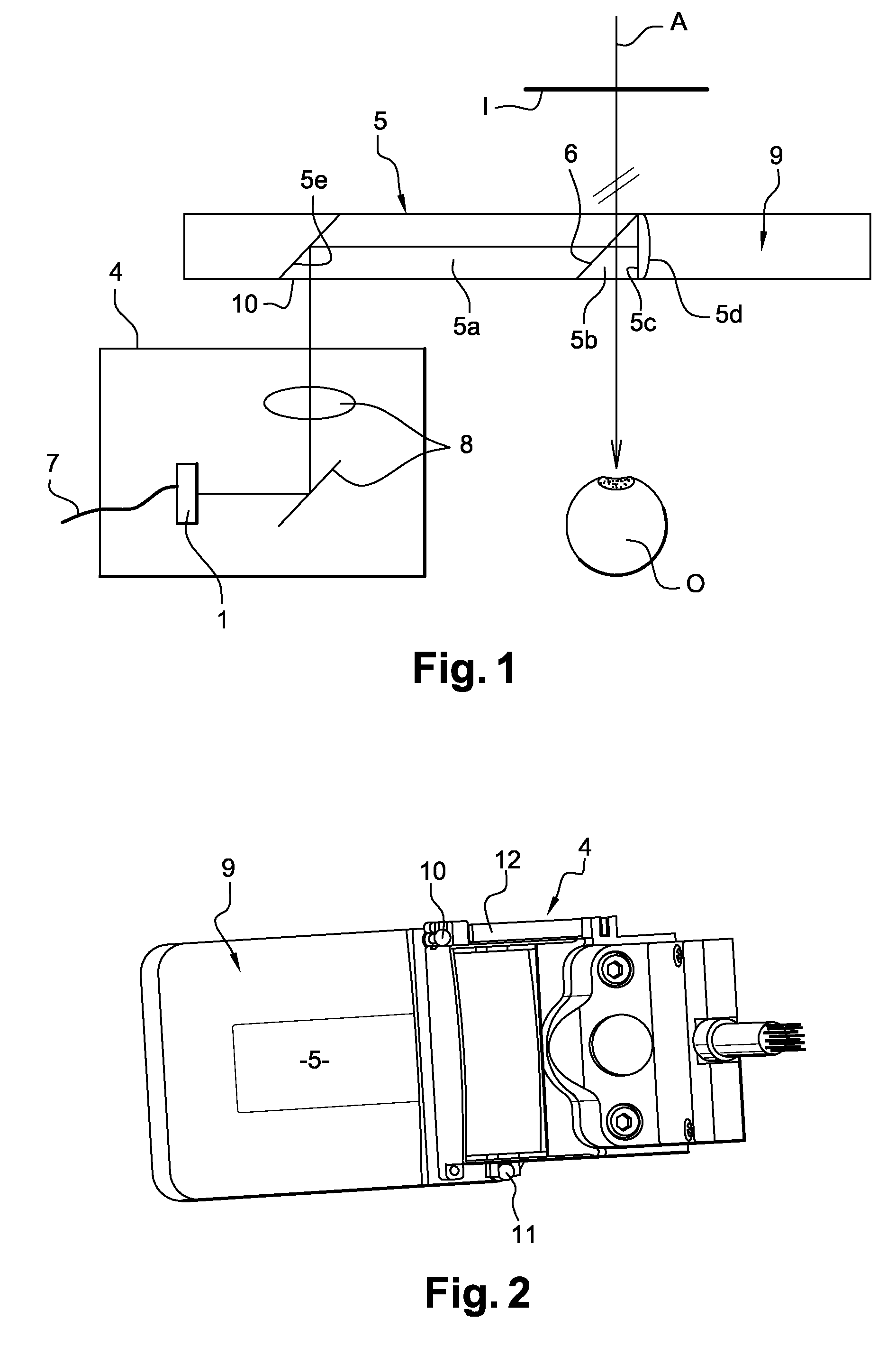
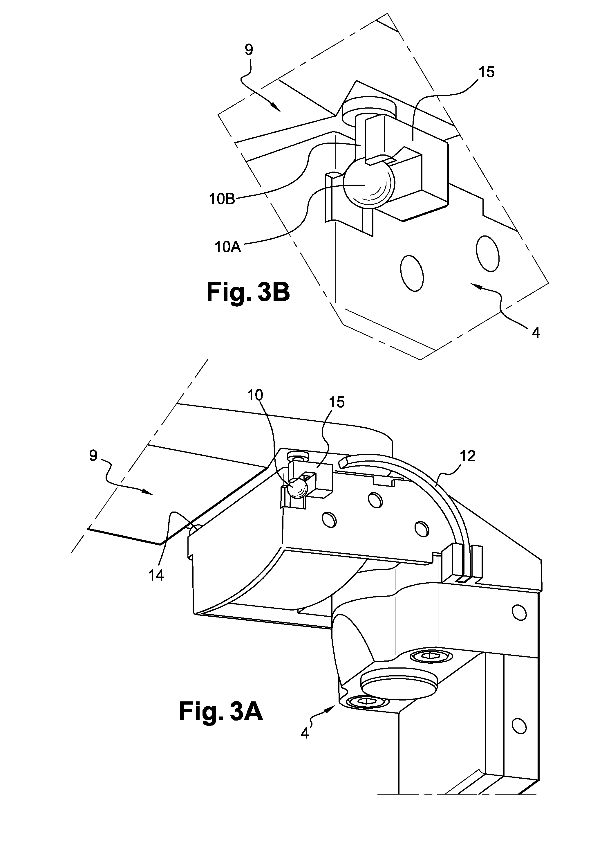
[0050]As shown in FIGS. 2 to 7, an ophthalmic display comprises an optical imager 5 for shaping light beams emitted by a light beam generator system 4, which beams are introduced into the imager via an inlet face, which imager then directs them towards the wearer's eye in order to enable an image to be viewed. The imager 5 is incorporated in a lens 9 of a pair of eyeglasses. Two hooks 10 and 11 anchored in bores of the lens 9, and arranged on the inlet face of the imager, are in reference positions relative to the imager 5 and the light beam generator system 4 includes an arrangement for connecting with the hooks, the connection between said system and the hooks being releasable.

[0051]The connection arrangement is machined or molded in a plate of the light beam generator system 4, which is preferably made of plastics material.

[0052]The hooks 10 and 11 are designed to be received in housings carried by the connection arrangement. Each of them is constituted by a sphere 10A, 11A dispo...


PUM


Abstract

The invention relates to a display comprising an optical imager (5) for shaping light beams emitted by a light beam generator system (4), said beams being introduced into said imager via an inlet face, and for directing the beams towards the eye (O) of a wearer in order to enable an image (I) to be viewed, two hooks (10, 11) being in reference positions relative to the imager, and said light beam generator system including a connection arrangement for connection to said hooks (10, 11), the connection between said system and said hooks being releasable and said hooks (10, 11) being designed to be received in housings carried by the connection arrangement. According to the invention, said housings are arranged in such a manner that said connection arrangement is assembled on said hooks by applying thrust against one of said hooks (11), by turning about said hook, and by snap-fastening onto the other hook (10).

Description

RELATED APPLICATIONS[0001]This application is a National Phase application of PCT / FR2008 / 051098, filed on Jun. 19, 2008, which in turn claims the benefit of priority from French Patent Application No. 07 56372, filed on Jul. 10, 2007, the entirety of which is incorporated herein by reference.BACKGROUND[0002]1. Field of the Invention[0003]The present invention relates to a display comprising an optical imager designed to enable information of the image or multimedia type to be projected, and preferably associated with a lens. The term “lens” is used herein to designate an optical system that is suitable in particular for being positioned in an eyeglass frame.[0004]2. Description of Related Art[0005]Patent U.S. Pat. No. 5,886,822 discloses a lens that presents a projection insert. Such a projection insert is constituted by an optical imager suitable for shaping light beams coming from an electronic and optical system for generating light beams on the basis of an electronic signal, of ...

Claims


Application Information

Patent Timeline
IPC IPC(8): G02B27/14G02B27/01G02B7/02G02B7/00
CPCG02B27/0176G02B27/017G02B27/0149G02B2027/0127G02B7/002G02B2027/0169G02B2027/0178
Inventor MOLITON, RENAUD
Owner ESSILOR INT CIE GEN DOPTIQUE
Learn More