Online monitoring method for metering performance of diaphragm gas meter
a diaphragm gas meter and monitoring method technology, applied in the field of gas metering, can solve the problems of prolonging the movement distance of the diaphragm, affecting and no meter of the two types has the function of judging the performance of their own meter, so as to achieve more accurate bases and improve the accuracy of metering a flow below the minimum flow of the gas meter.
- Summary
- Abstract
- Description
- Claims
- Application Information
AI Technical Summary
Benefits of technology
Problems solved by technology
Method used
Image
Examples
embodiment 1
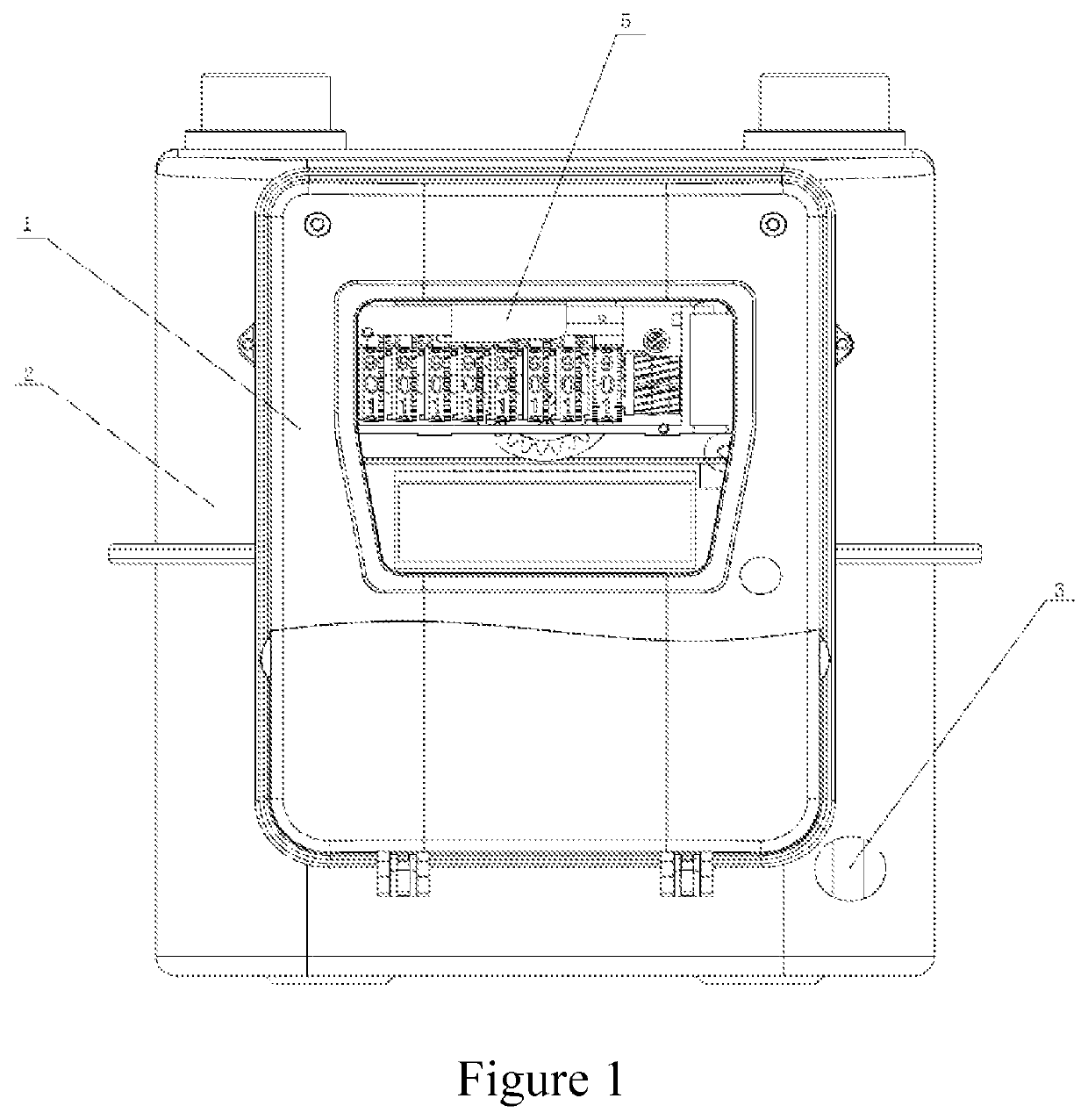
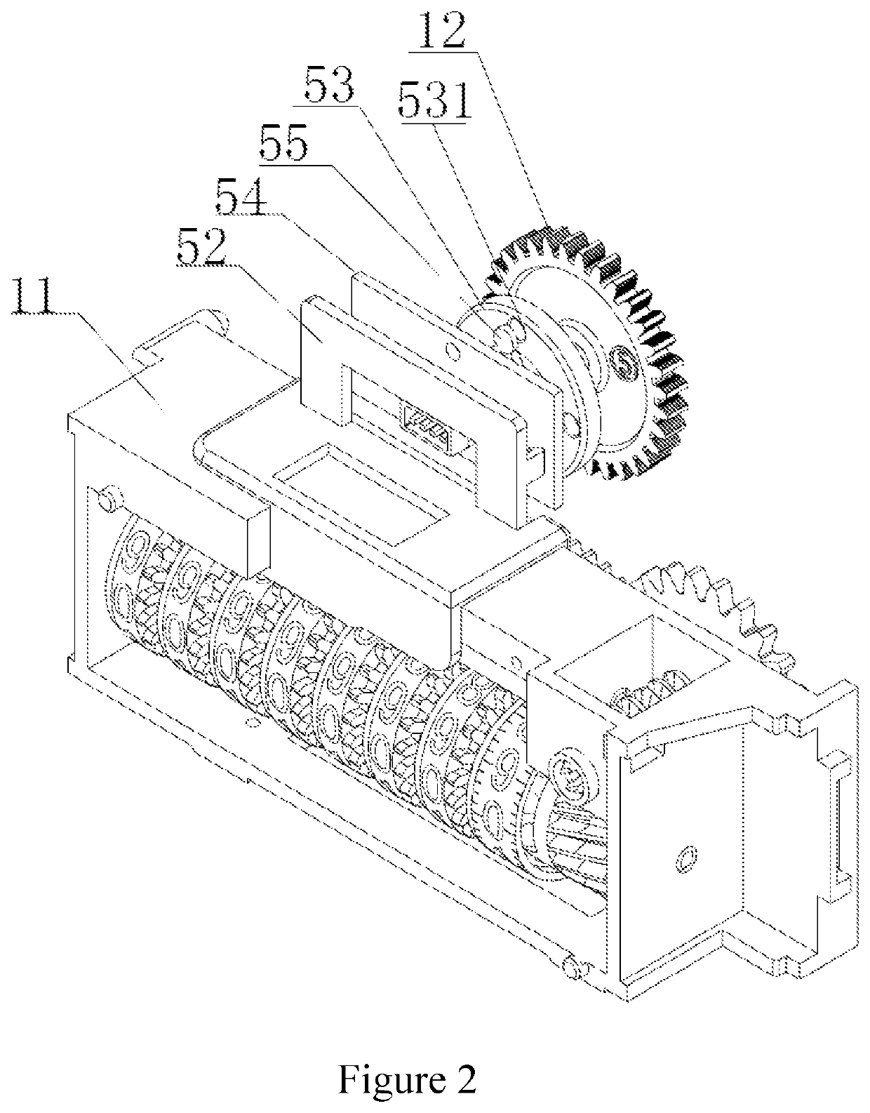
[0025]According to an online monitoring method for the metering performance of a diaphragm gas meter, an electromechanical conversion device 5 is mounted outside a cavity of a gas meter housing 2 (as shown in FIG. 1). A metering bin 1 is arranged outside the gas meter. A counter 11 and an outer driving gear 12 directly magnetically coupled to a diaphragm rotating shaft gear in a meter core 3 are arranged in the metering bin 1. A magnetic turntable 53 is embedded onto the outer driving gear 12 and rotates coaxially. A bracket 52 is fixedly mounted on the counter 11. A magnetic switch PCB 54 is perpendicularly mounted on the bracket 52 and is parallel to a plane of the magnetic turntable 53. Magnets 55 are arranged on the magnetic turntable 53. A magnetic switch is welded on the magnetic switch PCB 54.
[0026]The electromechanical conversion device 5 (as shown in FIG. 2) includes the bracket 52, the magnetic turntable 53, the magnetic switch PCB 54 and the magnets 55.
[0027]Rotation of t...
embodiment 2
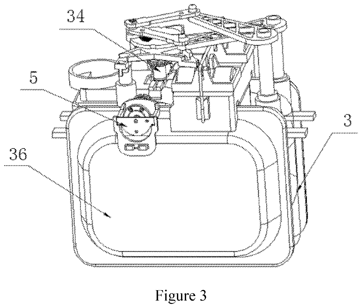
[0032]According to an online monitoring method for the metering performance of a diaphragm gas meter, an electromechanical conversion device 5 is mounted in a cavity of a gas meter housing 2 (as shown in FIG. 3). A meter core 3 in the cavity of the gas meter is provided with a diaphragm rotating shaft 34 and a diaphragm rotating shaft gear is arranged on the diaphragm rotating shaft 34. A transmission gear 51 is meshed with the diaphragm rotating shaft gear. Magnets 55 are arranged on a magnetic turntable 53. A magnetic switch is welded on a magnetic switch PCB 54. The magnetic switch PCB 54 is perpendicularly mounted on a bracket 52 and is parallel to a plane of the magnetic turntable 53.
[0033]The electromechanical conversion device 5 (as shown in FIG. 4) includes the transmission gear 51, the bracket 52, the magnetic turntable 53, the magnetic switch PCB 54 and the magnets 55. Rotation of the magnetic turntable 53 for a circle corresponds to discharge of gas of a rotary volume by ...
PUM
 Abstract
Description
Claims
Application Information
 - R&D
- Intellectual Property
- Life Sciences
- Materials
- Tech Scout
- Unparalleled Data Quality
- Higher Quality Content
- 60% Fewer Hallucinations
Browse by: Latest US Patents, China's latest patents, Technical Efficacy Thesaurus, Application Domain, Technology Topic, Popular Technical Reports.
© 2025 PatSnap. All rights reserved.Legal|Privacy policy|Modern Slavery Act Transparency Statement|Sitemap|About US| Contact US: help@patsnap.com


