Surge protection device

a surge protection and surge technology, applied in the direction of automatic disconnection emergency protection arrangements, protective switch operating/release mechanisms, electrical equipment, etc., can solve the problems of not being able to operate the circuit breaker, not being able to permanently disconnect the equipment, and not being able to restore the surge protection device. to achieve the effect of improving the availability of equipmen

Active Publication Date: 2021-03-09
KHOSLA SANJEEV +1
View PDF4 Cites 0 Cited by
  • Summary
  • Abstract
  • Description
  • Claims
  • Application Information

AI Technical Summary

Benefits of technology

[0027]wherein, the said line switch (7) operates to disconnect the line (2) from the load (4) under high voltage condition caused by surges and / or any other means to disconnect the load (4) and any surge / spike arrestor (8) down the line before its operating parameters are exceeded and restores the connection when voltage input is in normal range, wherein the said surge protection device comprises of in-built controlled power source to operate the line switch (7) with self-restoring circuit breaker such that the controlled power source used to operate the line switch (7) constitutes voltage control means (10) which constitutes a fast bridge rectifier (16) to ensure unipolar feed to operate the line switch (7) through peak detector (11), a attenuator-cum-spike shunt (15) to ensure adequate protection to the voltage control means without causing much time delay, the said peak detector (11) to ensures fast operation on the negative or positive (made unidirectional / unipolar) rising of the surge in either direction beyond the normal operating range, a filter cum time delay (14) desisting the surge from building up in time to pass through it towards the SPD output and the delay is further increased as the surge passes over the spike / surge arrestor (8), a power supply (12) quickly armed to a value of upper limit to operate the line switch (7) in fastest mode without damaging it.
[0039]Another embodiment of the present invention is to provide a surge protection device (3), wherein the said voltage control means has a fast bridge rectifier (16) and attenuator-cum-spike shunt (15) to increase the upper voltage operating range of the line switch (7).
[0043]Still another embodiment of the present invention is to provide a surge protection device (3), wherein the load has a line switch (7) with faster operating time than the operating time of the in-built surge / spike arrestor.
[0047]Yet still another embodiment of the present invention is to provide a surge protection device (3), wherein, optionally, a controlled power source (6) is used to work as an energy source required to prevent temporary disruption of energy supply to the load / equipment during the temporary disconnection caused by the line switch (7) operation.
[0051]One of the object of the present invention is to provide an improved surge protection device comprising a fast acting, self-restoring circuit breaker, preferably, along with surge arrestor / absorber to improve the availability of the equipment in use with power source affected with surges / spikes.

Problems solved by technology

The conventional surge protection devices are non-self restoring.
The ones which have NO / NC switches are not, in fact, enough for electronic devices.
Further, though they can disconnect and protect the equipment in accordance with their capacity, in use under high voltage operation, however, under long duration surges, they cannot rule out the possibility getting incapacitated or operating the circuit breaker and permanently disconnecting the equipment in use, or even operation of Metal Oxide Varistor (MOV) or equivalent type surge / spike arrestor provided in the equipment to operate and render the equipment inoperational or which even lead to failure of electronic components in the equipment where power sources are frequently affected by spikes and surges.
Surges and spikes are generated in electrical supply systems where loads get switched in and out, particularly inductive loads and also in comprehensive installations during the course of maintenance work or due to any degradation over time as a result of phase decompensation, which is usually caused by the neutral conductor breaking, its faulty connection or faults in transformer centres.
A surge protector attempts to limit the voltage supplied to an electric device by either blocking or by shorting to ground any unwanted voltages above a safe threshold, wherein, such operation is limited to a number of times after which breakdown is imminent.
The primary power source is AC supply and is often affected by surges and spikes on it which makes the electronic equipment vulnerable.
However, there is no such protection available which will ensure that the equipment in use is not affected or made inoperative.
However, they are significantly higher in price, besides being more vulnerable to failure on surges and spikes.
However, they have their boundaries of performance beyond which they fail and the protected device is then affected or damaged or becomes dysfunctional.
This not only causes monetary loss but also creates inconvenience and discomfort with respect to the utility it is serving.
The above suffers on two accounts (a) the spikes of duration smaller than the response time of the switch go on to effect the equipment being protected, (b) the surge if greater than the absorption power of the SPD will cause SPD to fail and thereby further exposing the equipment to the surge.
It is pertinent to mention that it is not desirable to have a short across the line in many applications as it is unsafe.
Further, the surge protection device failure if not detectable in the operation would eventually lead to exposure of the equipment to surges after the failure of the surge protection mechanism in the SPD (Surge Protection Device).
It is pertinent to mention here that it is not desirable to have a short across the line in many applications as it is unsafe.
Further, the surge protection device failure if not detectable in the operation would eventually lead to exposure of the equipment to surges after the failure of the surge protection mechanism in the SPD (Surge Protection Device).
In many configurations the effect of surge is caused or increased when the cable going into the field to feed the equipment, particularly underground, becomes leaky to earth, even though it may have been carrying an isolated supply but due to such leakage has become prone to surges and affect of noise, and prone to causing equipment / equipment function failure.

Method used


Image

  • Surge protection device
  • Surge protection device
  • Surge protection device

Examples


Embodiment Construction

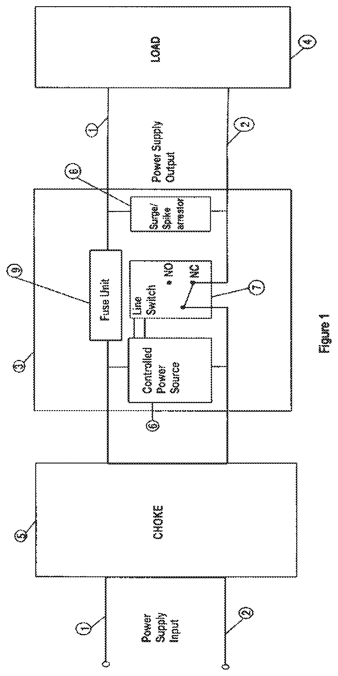
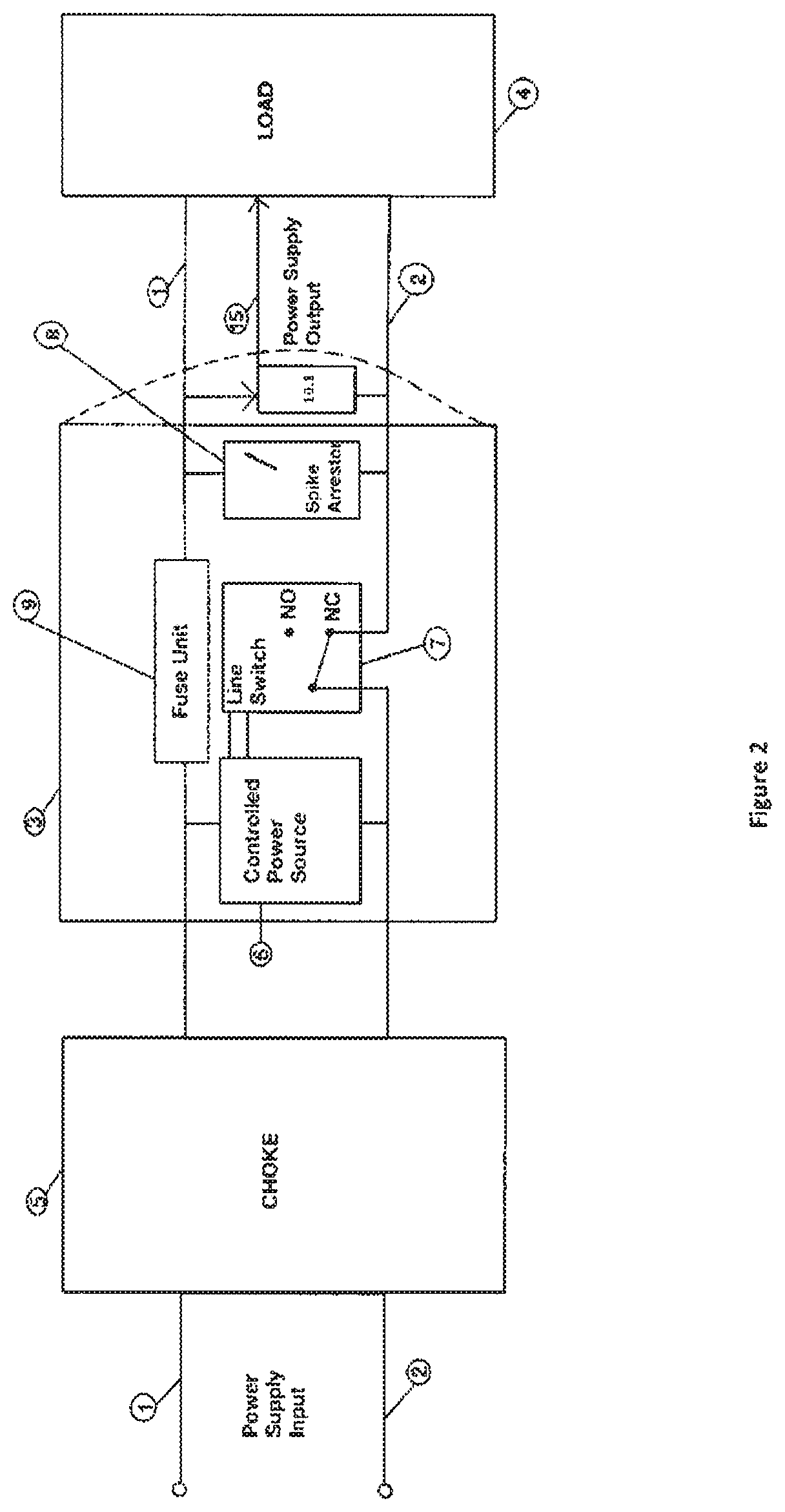
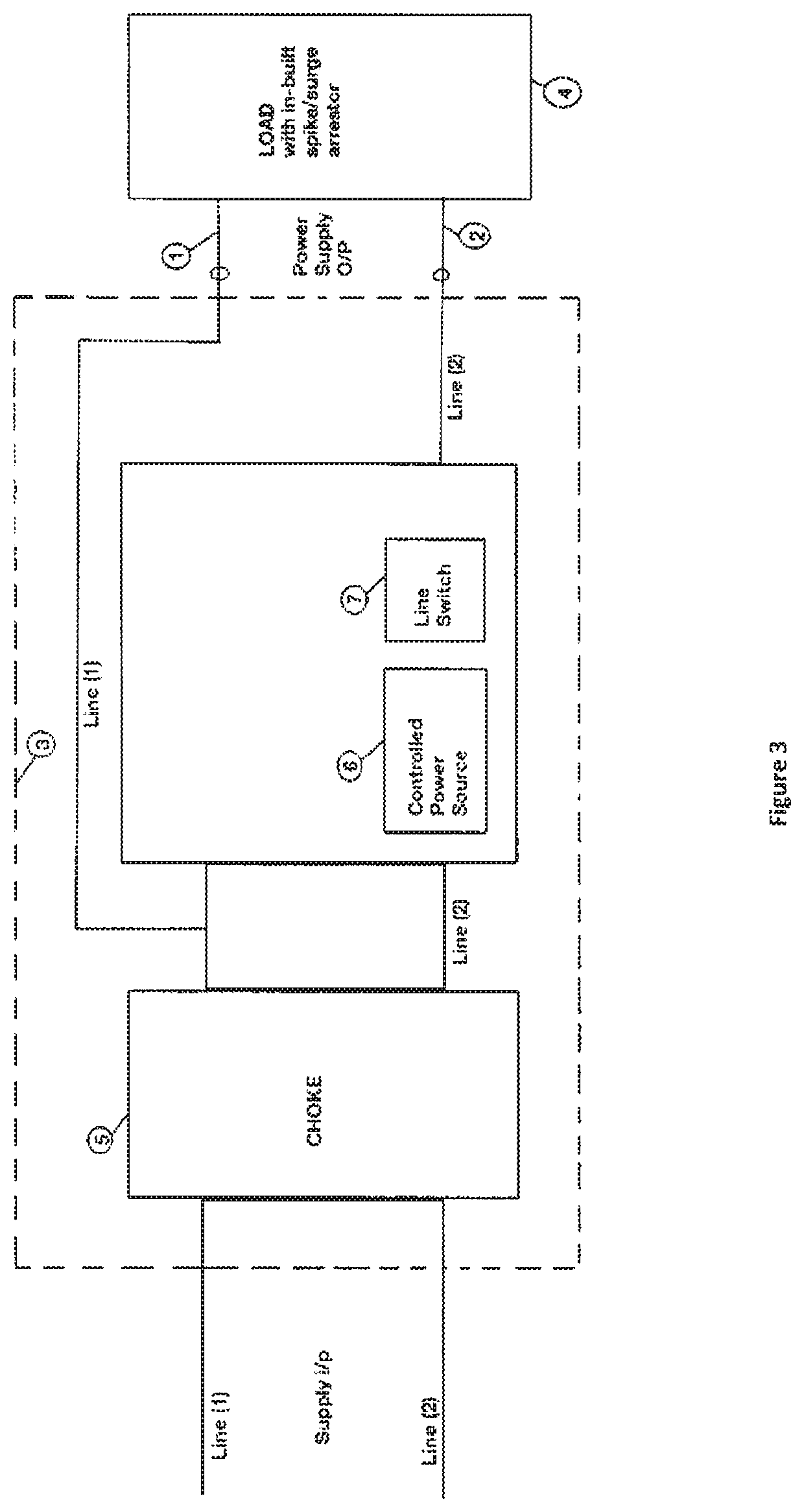
[0060]The present invention provides an improved surge protection device (SPD) for an electronic equipment comprising a self-restoring circuit breaker preferably along with surge arrestor / absorber to improve the availability of the equipment in use with power source affected with surges / spikes.

[0061]The circuit breaker can be a fast acting relay or any means having a NO / NC contact(s) made to operate through the voltage control means such that it opens before the internal and / or external surge / spike arrestor(s), if the system breakdown voltages are crossed. It not only protects the equipment but also the surge absorbers / spike arrestors like MOV or other devices being used in the system so that their operating life is substantially enhanced or not affected.

[0062]FIG. 1 shows input supply line 1 and 2 passing through the external optional choke (needed more for AC supply circuits), both the lines then connecting to the SPD(3), having a controlled power source (6) to detect the conditio...


PUM


Abstract

The invention relates to an improved surge protection device comprising a fast acting, self-restoring circuit breaker, preferably, along with surge arrestor / absorber to improve the protection and availability of the equipment which is in use with power source affected with surges / spikes which otherwise would have operated the spike / surge arrestor in-built in the equipment that would have led to its non-availability, and protection for equipment that may or may not be having in-built overcurrent, surge protection devices.

Description

FIELD OF INVENTION[0001]The invention relates to an improved surge protection device comprising a fast acting, self-restoring circuit breaker, preferably, along with surge arrestor / absorber to improve the protection and availability of the equipment which is in use with power source affected with surges / spikes, overvoltage which otherwise would have damaged the equipment and / or operated the spike / surge arrestor in-built in the equipment that would have led to its non-availability, and protection for equipment that may or may not be having in-built overcurrent surge protection devices.BACKGROUND AND PRIOR ART[0002]Surge protection is a big concern even today where electronic devices are used. The conventional surge protection devices are non-self restoring. Thus, their operation makes the equipment in operational. The ones which have NO / NC switches are not, in fact, enough for electronic devices. Further, though they can disconnect and protect the equipment in accordance with their c...

Claims


Application Information

Patent Timeline
Patent Type & Authority Patents(United States)
IPC IPC(8): H02H3/00H02H3/22H01H71/12
CPCH02H3/22H01H71/12H02H3/20
Inventor KHOSLA, SANJEEVKHOSLA, AARTI
Owner KHOSLA SANJEEV
Why Eureka
Try Eureka