Pressing device for toroidal continuously variable transmission

a technology of pressing device and toroidal transmission, which is applied in the direction of friction gearing, belt/chain/gearing, friction gearing, etc., can solve the problems of increasing the dimensions and thus the weight of the pressing device, reducing the radius of curvature, and generating large frictional force easily

Active Publication Date: 2021-03-16
NSK LTD +1
View PDF22 Cites 0 Cited by
  • Summary
  • Abstract
  • Description
  • Claims
  • Application Information

AI Technical Summary

Benefits of technology

[0033]With the pressing device for toroidal continuously variable transmission of the present invention, it is possible to reduce hysteresis that occurs between torque and a pressing force. That is to say, the intermediate sliding member that is separate from the roller is arranged in at least one location of a portion between the end surface on the outside in the radial direction of the retainer of the roller arranged on the outermost side in the radial direction of the retainer and the inside surface of the pocket on the outside in the radial direction of the retainer, and a portion between the end surface on the outside in the radial direction of the retainer of one roller of the adjoining rollers in the radial direction of the retainer of the two or more rollers and the end surface on the inside in the radial direction of the retainer or the other roller of the adjoining rollers, and therefore the contact area of the sliding contact portion between the intermediate sliding member and the inside surface of the respective pockets or the end surface of the roller is made smaller than the contact area of the sliding contact portion in a case where the intermediate sliding member is not provided and there is direct sliding contact between the end surface of the roller and the inside surface of the pocket, or between the end surfaces in the axial direction of the adjoining rollers in the radial direction of the retainer. As a result, frictional torque that occurs at the sliding contact portion between the intermediate sliding member and the end surface in the axial direction of the roller or the side surface in the radial direction of the pocket may be made smaller than in the case where the intermediate sliding member is not provided. Accordingly, with the pressing device for toroidal continuously variable transmission of the present invention, it is possible to reduce hysteresis that occurs between torque and a pressing force.
[0034]Particularly, in the pressing device for toroidal continuously variable transmission of the present invention, the intermediate sliding member is formed separately from the roller, so the design of the intermediate sliding member is not restricted by the roller body. Therefore, in a case where the tip end surface of the intermediate sliding member is configured by a spherical convex surface, it becomes possible to reduce the radius of curvature of the spherical convex surface, and compared with a case where the spherical convex surface is directly formed on the end surface as in a conventional roller, the contact area of the sliding contact portion can be reduced, the sliding contact portion can be configured by point contact, and the hysteresis can be more effectively reduced.
[0035]Moreover, by making the intermediate sliding member separate, it is possible for the material of the intermediate sliding member to be different than the material of the roller. Therefore, the hardness of the material of the intermediate sliding member can be made lower than the hardness of the material of the roller, so in comparison with a case where there is sliding contact between end surfaces of rollers made of bearing steel, the frictional force can be effectively reduced, and thus, the hysteresis can be effectively reduced.
[0036]Furthermore, by making the intermediate sliding member a separate member, even when a structure for attaching the intermediate sliding member is provided on an end surface on the outside in the radial direction of the retainer of the roller, the outermost surface in the radial direction of the retainer of this end surface is configured by a flat surface that extends in a direction orthogonal to the center axis of the roller, or in other words, this end surface may be made parallel to the opposing end surface of the roller which is adjacent thereto. Therefore, even in a case where grinding is performed on the rolling surfaces of a plurality of rollers at the same time, the plurality of rollers can be stably placed, and the rolling surface of the respective rollers may be made to have favorable processing accuracy. This also makes it possible to reduce the loss due to hysteresis that accompanies a local increase in contact pressure on the rolling surface.

Problems solved by technology

However, during operation of the toroidal continuously variable transmission, a centrifugal force acts on the roller as the retainer rotates, so a large frictional force is easily generated at the sliding contact portions between the end surfaces in the axial direction of the rollers, and at the sliding contact portions between the outside surfaces in the radial direction of the pockets and the end surfaces in the axial direction of the rollers that face the outside surfaces in the radial direction of the pockets.
When the generated pressing force of the pressing device becomes excessively large, not only does it become necessary to increase the dimensions and thus the weight of the pressing device, but also those of the overall toroidal continuously variable transmission in which the pressing device is installed.

Method used


Image

  • Pressing device for toroidal continuously variable transmission
  • Pressing device for toroidal continuously variable transmission
  • Pressing device for toroidal continuously variable transmission

Examples


first example

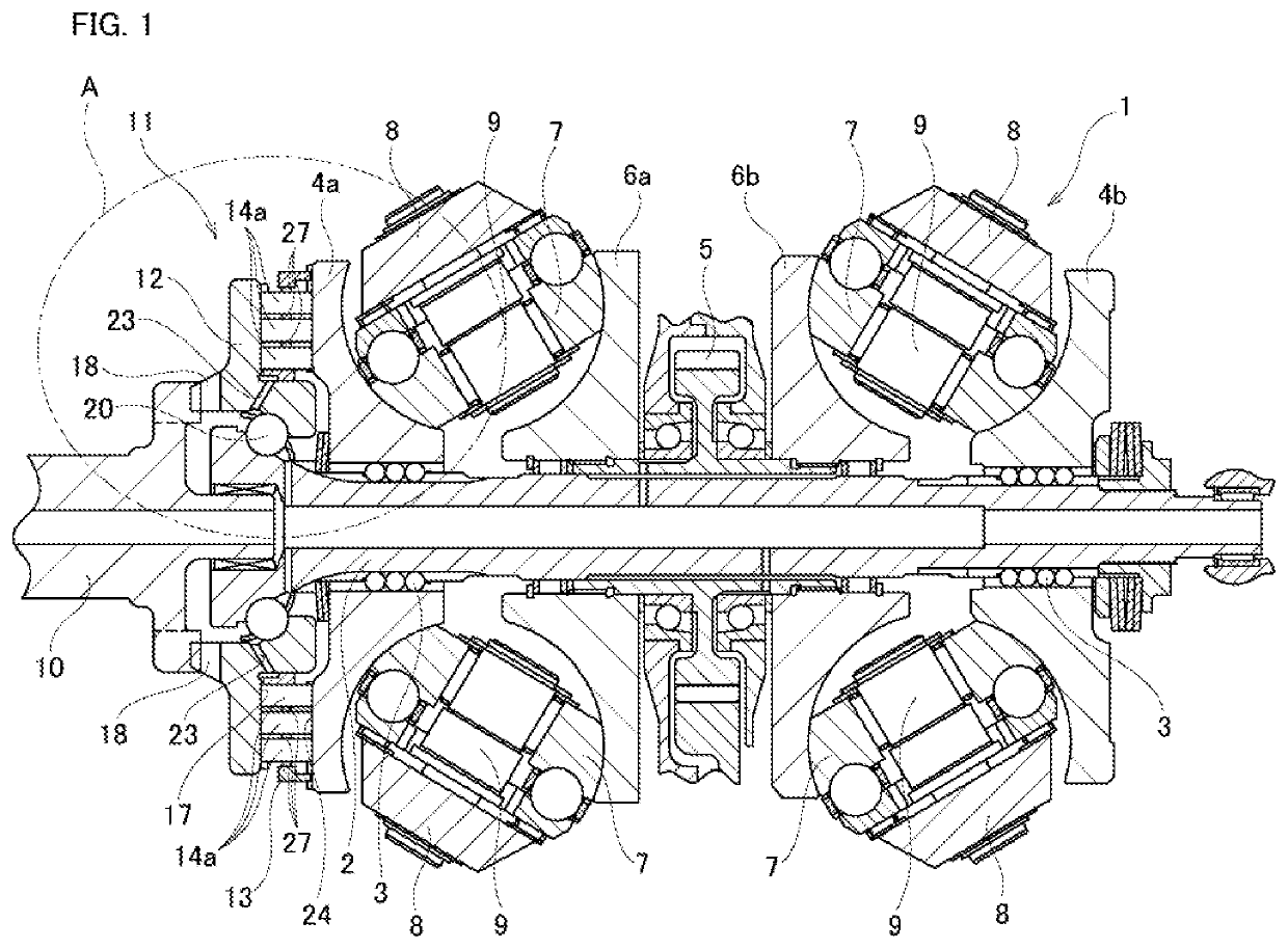
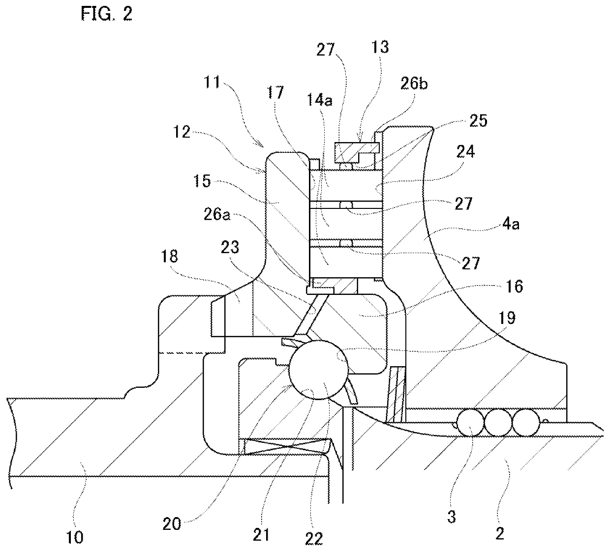
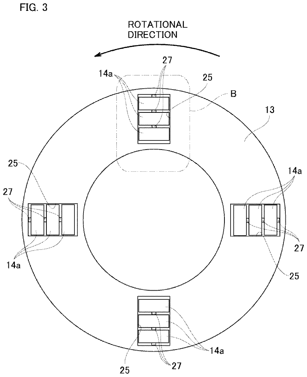
[0055]FIG. 1 to FIG. 6 illustrate a first example of an embodiment of the present invention. The toroidal continuously variable transmission 1 is a double cavity type and includes a pair of outside disks 4a, 4b and inside disks 6a, 6b, between which two cavities are formed in which power rollers 7 are arranged. The pair of outside disks 4a, 4b are supported around both end portions in the axial direction of the input shaft 2 via ball splines 3 so as to be able to rotate coaxially and synchronously with each other. The outside disks 4a and 4b have toroidal curved surfaces that are concave surfaces having an arc-shaped cross section on the inside in the axial direction facing each other. However, the present invention can also be applied to pressing device for a single-cavity toroidal continuously variable transmission that includes one input-side disk and one output-side disk.

[0056]A gear 5 is supported around a middle portion in the axial direction of the input shaft 2 so as to be a...

second example

[0082]FIG. 7 and FIG. 8 illustrate a second example of an embodiment of the present invention, which is a modification of the first example of an embodiment. In this example, as in the case of the first example of an embodiment, intermediate sliding members 27a are attached to one end surface in the axial direction (upper end surface in FIG. 7 and FIG. 8) of the respective rollers 14b. However, in this example, the shape of the respective intermediate sliding members 27a is different than in the first example.

[0083]The intermediate sliding member 27a has a substantially cylindrical shape on the base side that is attached to one end surface in the axial direction of the roller 14b, however a spherical convex surface 45 is formed on the tip end side. As a result, the intermediate sliding member 27a is such that instead of surface contact with a mating surface, the tip portion thereof can be brought into point contact with the mating surface. Here, in order to reduce hysteresis, or in ...

third example

[0085]FIG. 9 illustrates a third example of an embodiment of the present invention, which is a modification of the first example. In this example, as in the first example, an intermediate sliding member 27b is attached to one end surface in the axial direction (upper end surface in FIG. 9) of the roller 14c. However, in this example, the shapes of the roller 14c and the intermediate sliding member 27b, and the manner of attachment of the intermediate sliding member 27b to the roller 14c are different from those in the first example.

[0086]The roller 14c has a convex portion 33 that projects in the axial direction at the center portion of one end surface in the axial direction. The tip end surface of the convex portion 33 is a flat surface that extends in a direction orthogonal to the center axis of the roller 14c, or in other words, parallel to the end surface in the axial direction of the roller 14c. The intermediate sliding member 27b includes a disk portion 34 and a cylindrical sh...


PUM


Abstract

Provided is a pressing device for toroidal continuously variable transmission capable of reducing hysteresis that occurs between torque and pressing force. An intermediate sliding member 27 is provided in at least one location of a portion between an end surface on the outside in the radial direction of the retainer 13 of the roller 14 arranged on the outermost side in the radial direction and an inside surface of the pocket 25 on the outside in the radial direction, and a portion between an end surface on the outside in the radial direction of the retainer 13 of one roller 14 of adjoining rollers 14 in the radial direction and an end surface on the inside in the radial direction of the retainer 13 of another roller 14. As a result, the contact area of a sliding contact portion 32 is made smaller than in a case where an intermediate sliding member 27 is not provided.

Description

TECHNICAL FIELD[0001]The present invention relates to a loading cam type pressing device for a toroidal continuously variable transmission installed in generators such as aircraft generators and the like, various kinds of industrial machinery such as pumps and the like, and vehicles including automobiles, construction machinery and the like.BACKGROUND ART[0002]A toroidal continuously variable transmission comprises an input-side disk and an output-side disk that are coaxially arranged to each other and that rotate relative to each other, and a plurality of power rollers that are held between these disks, and the toroidal continuously variable transmission is configured so that power is transmitted from the input-side disk to the output-side disk via the power rollers. In a toroidal continuously variable transmission, it is possible to adjust the transmission ratio between the input-side disk and the output-side disk by changing the inclination angle of the power rollers.[0003]During...

Claims


Application Information

Patent Timeline
Patent Type & Authority Patents(United States)
IPC IPC(8): F16H15/38
CPCF16H15/38F16H15/36F16H57/049F16H2015/383
Inventor ITAGAKI, HIROFUMIKITA, MASAHIROMATSUDA, KIPPEITANAKA, KENICHIROIMAI, HIDEYUKIKOMATSU, KENJI
Owner NSK LTD
Why Eureka
Try Eureka