Seatbelt device for vehicle
a seatbelt and vehicle technology, applied in the field of seatbelt devices for vehicles, can solve the problems of complex structure for switching operation modes, inability to obtain the restraint load in accordance with the situation, and the occupant's body side and the emergency, etc., to achieve the effect of suppressing complexity and large size of the retractor's structur
- Summary
- Abstract
- Description
- Claims
- Application Information
AI Technical Summary
Benefits of technology
Problems solved by technology
Method used
Image
Examples
embodiment 1
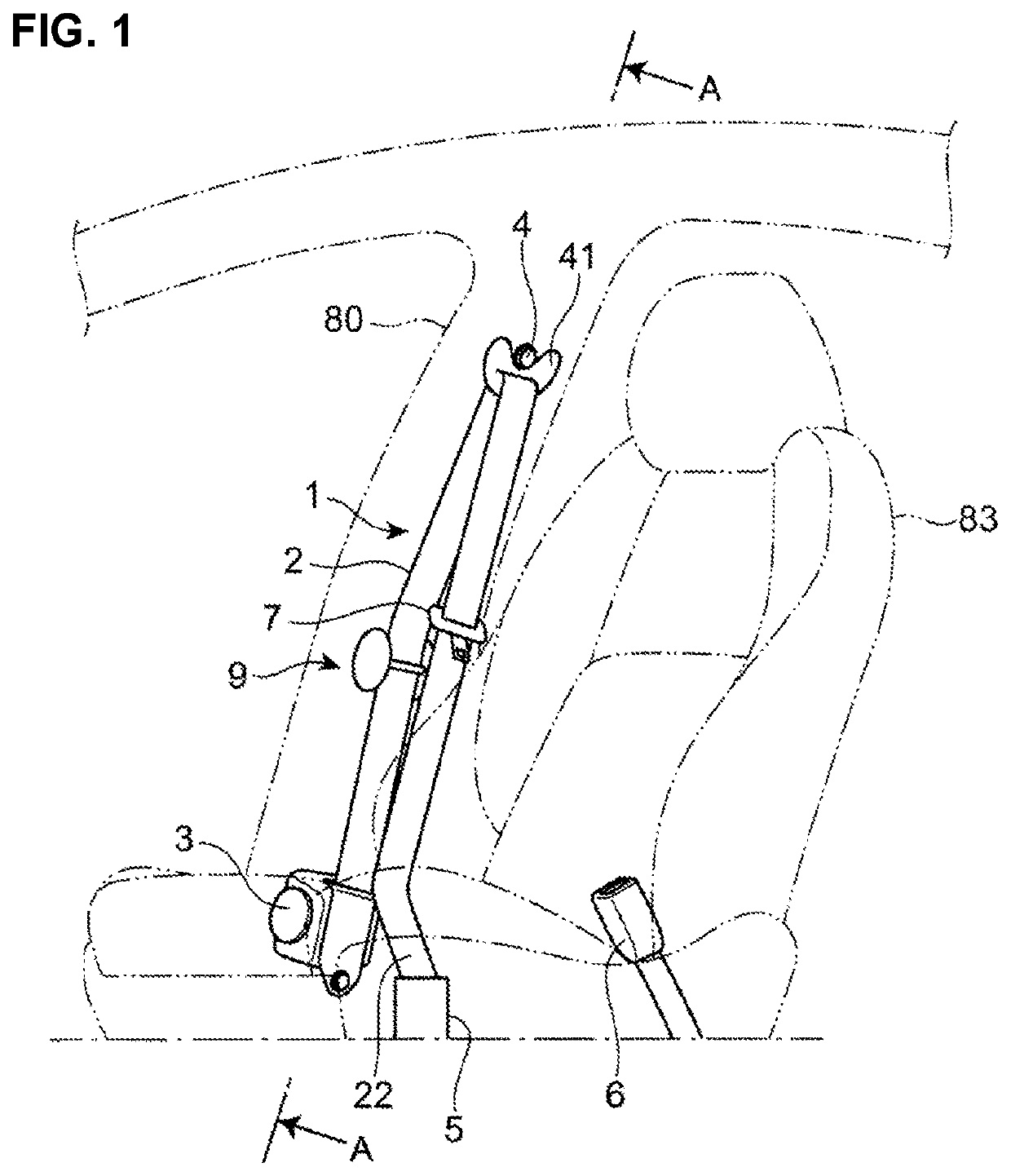
[0044]As shown in FIG. 1, the seatbelt device 1 is a so-called three-point type of seatbelt which is provided at a front seat of a vehicle. The seatbelt device 1 comprises a belt 2, a retractor 3, an upper anchor 4, a lower anchor 5, a buckle 6, and a tongue plate 7.
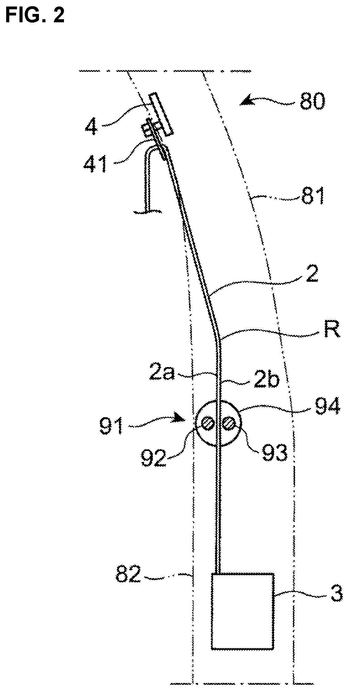
[0045]The retractor 3 is arranged near a lower end of a center pillar 80. The upper anchor 4 is arranged near an upper end of the center pillar 80. A D ring 41 is attached to the upper anchor 4. A lower anchor 5 is arranged adjacently to an outward side, in a vehicle width direction, of a seat 83. The buckle 6 is arranged adjacently to an inward side, in the vehicle width direction, of the seat 83.
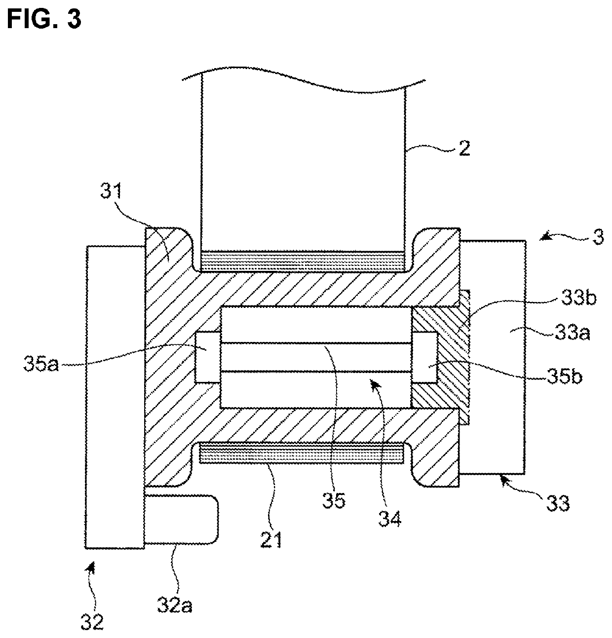
[0046]One end portion 21 of the belt 2 is supported at a spool 31 (see FIG. 3) of the retractor 3 so that it is wound up, and the other end portion 22 of the belt 2 is fixed to a vehicle floor via the lower anchor 5 and the like. The D ring 41 and a tongue plate 7 are provided such that the belt 2 is inserted into these members...
embodiment 2
[0101]Next, a seatbelt device for a vehicle according to the second embodiment will be described referring to FIGS. 13-16. In the second embodiment, the same structures as the first embodiment are denoted by the same reference characters in FIGS. 13 and 14, descriptions of which are omitted.
[0102]As shown in FIG. 13, the restraint-load applying device 9 of the seatbelt device for the vehicle comprises a driving mechanism 200 which is different from the driving mechanism 96 of the first embodiment. Specifically, the driving mechanism 200 of the second embodiment comprises a motor 296 as a driving resource. The operation of the motor 296 is controlled based on control signals from the above-described control unit 100 (see FIG. 8).
[0103]The driving mechanism 200 of the second embodiment comprises a driving gear 298 which is fixed to an output shaft 297 of the motor 296, an intermediate gear 299 which engages with the driving gear 298, and a driven gear 300 which is fixed to the rearwar...
PUM
 Abstract
Description
Claims
Application Information
 - R&D
- Intellectual Property
- Life Sciences
- Materials
- Tech Scout
- Unparalleled Data Quality
- Higher Quality Content
- 60% Fewer Hallucinations
Browse by: Latest US Patents, China's latest patents, Technical Efficacy Thesaurus, Application Domain, Technology Topic, Popular Technical Reports.
© 2025 PatSnap. All rights reserved.Legal|Privacy policy|Modern Slavery Act Transparency Statement|Sitemap|About US| Contact US: help@patsnap.com


