Multielectrode sensor for concentration and depth measurements in molten salt

a multi-electrode sensor and concentration measurement technology, applied in the direction of measurement devices, instruments, material electrochemical variables, etc., can solve the problems of inability to know whether or not a current response is large, technique is slow, loss of non-conductive coating, etc., to save time, accurate results, and the effect of reducing the frequency of concentration measurements

Active Publication Date: 2021-03-23
THE UNITED STATES AS REPRESENTED BY THE DEPARTMENT OF ENERGY
View PDF19 Cites 2 Cited by
  • Summary
  • Abstract
  • Description
  • Claims
  • Application Information

AI Technical Summary

Benefits of technology

[0008]A principal advantage of the sensor of the invention is the speed by which measurements may be taken. Furthermore time is saved because cleaning and relaxation and resting of selected electrodes can occur while testing is occurring on other electrodes. The frequency of concentration measurements can be reduced by more than 60% while still achieving accurate results with low statistical uncertainty.

Problems solved by technology

As the high radiation environment and high temperatures of molten salt nuclear systems make many common process monitoring techniques untenable, electroanalytical approaches have received considerable attention for this application.
One of the largest issues is the determination of the surface area of the electrodes in the molten salt; the area is required to be known in order to calculate concentrations because the current response is proportional to both the concentration and the available electrode area.
Hence, without accurate determination of the electrode area, it is impossible to know whether or not a current response is large because of a correspondingly large reactant concentration or because there's simply a large surface area available for the electrochemical reaction to occur.
This technique is slow and requires repeated removal of the electrode to make measurements of the film.
These barrier coatings, however, are limited to narrow potential ranges and generally are only stable for very limited times in corrosive molten salt environments which often results in either a loss of the non-conductive coating or in the formation of a conductive layer on the surface of the non-conductive coating.

Method used


Image

  • Multielectrode sensor for concentration and depth measurements in molten salt
  • Multielectrode sensor for concentration and depth measurements in molten salt
  • Multielectrode sensor for concentration and depth measurements in molten salt

Examples


Embodiment Construction

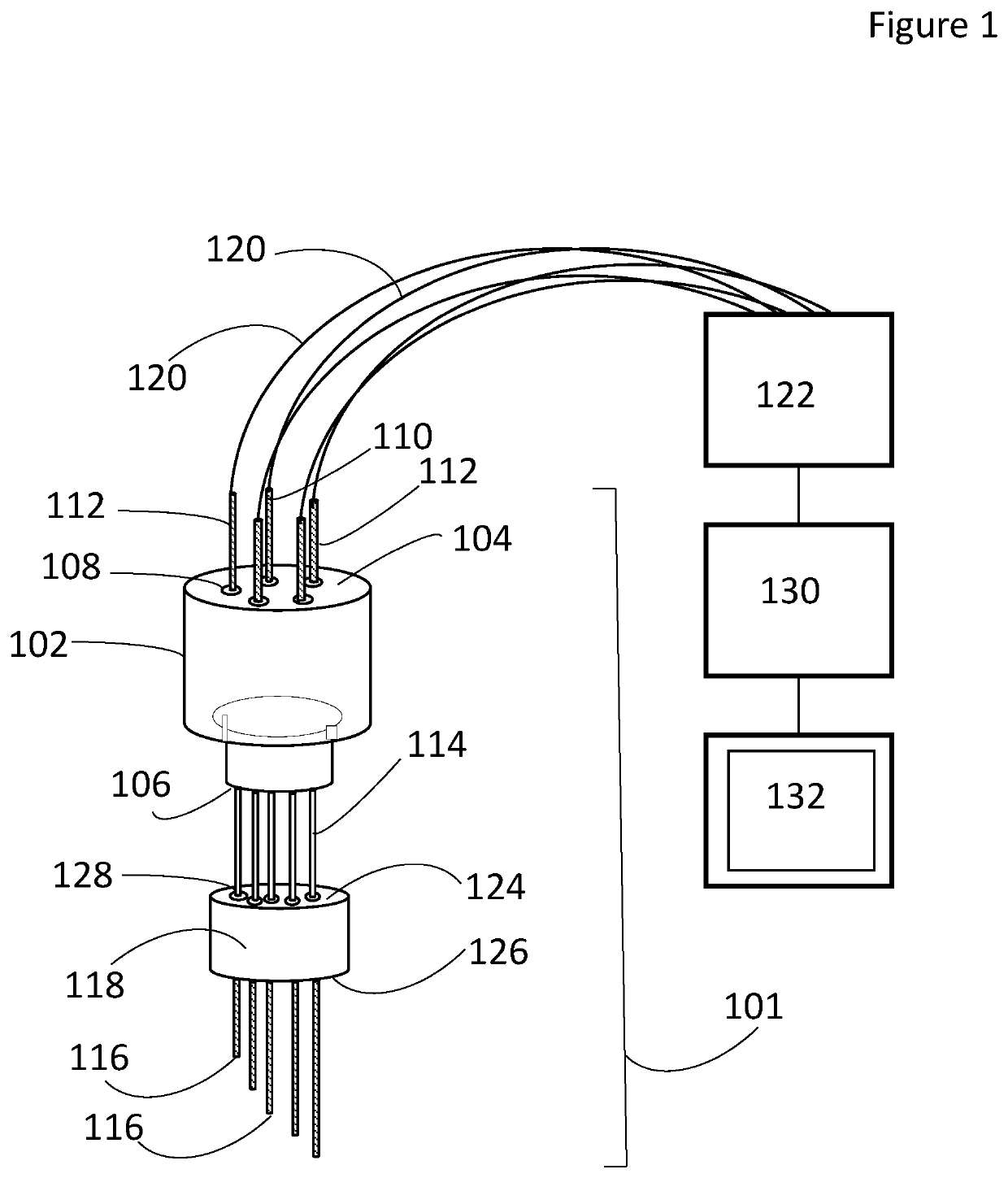
[0017]The multi electrode sensor 100 provides in-situ, real time measurements for molten salts and other process fluids. For example, the sensor can provide real-time concentration and salt level measurements for nuclear systems such as molten salt reactors, nuclear reprocessing facilities utilizing molten salts and concentrated solar power systems. Concentration and salt level measurements are crucial for process monitoring to ensure proper chemistry and product quality and for nuclear material safeguards (i.e., material accountancy of salts containing nuclear materials).

[0018]As illustrated in FIG. 1, the sensor has an array 101. The array includes a plug 102. The plug has a top surface 104 and a bottom surface 106. Several openings 108 extend from the top surface 104 to the bottom surface 106. Each of the openings 108 is spaced equidistant from adjacent openings 108. The plug 102 is formed of a nonconductive material. In one embodiment the plug 102 is ceramic.

[0019]The array 101 ...


PUM

PropertyMeasurementUnit
currentaaaaaaaaaa
unit depthaaaaaaaaaa
lengthaaaaaaaaaa

Abstract

A multi electrode sensor that provides in-situ, real time measurements for molten salts and other process fluids such as real-time concentration and salt level measurements for nuclear systems such as molten salt reactors, nuclear reprocessing facilities utilizing molten salts and concentrated solar power systems. The sensor has multiple electrodes with unique lengths which are connected to a potentiostat. Measurements are taken when the electrodes are immersed in the process fluid.

Description

GOVERNMENT INTERESTS[0001]The United States Government has rights in this invention pursuant to Contract No. DE-AC02-06CH11357 between the U.S. Department of Energy (DOE) and UChicago Argonne, LLC.FIELD OF THE INVENTION[0002]The present invention relates to in-situ real-time concentration and salt level measurements for molten salt systems.BACKGROUND OF THE INVENTION[0003]As the high radiation environment and high temperatures of molten salt nuclear systems make many common process monitoring techniques untenable, electroanalytical approaches have received considerable attention for this application. Electroanalytical techniques are based on measurements of the amount of current that flows through an electrode immersed in the molten salt when a specific potential waveform has been applied to that electrode. Electroanalytical methods have been used in the past for analysis of molten salt systems, but these approaches have a number of shortcomings.[0004]One of the largest issues is th...

Claims


Application Information

Patent Timeline
Patent Type & Authority Patents(United States)
IPC IPC(8): G01N27/28G01N27/48G01N27/416
CPCG01N27/283G01N27/4166G01N27/48
Inventor HOYT, NATHANIEL C.WILLIAMSON, MARK A.WILLIT, JAMES L.
Owner THE UNITED STATES AS REPRESENTED BY THE DEPARTMENT OF ENERGY
Why Eureka
Try Eureka