Clutch control device

a control device and clutch technology, applied in the direction of non-mechanical actuated clutches, clutches, accumulations, etc., can solve the problems of judder vibration, inability to suppress judder vibration, etc., and achieve the effect of reducing or preventing judder vibration

Active Publication Date: 2021-03-30
NIDEC TOSOK CORP
View PDF16 Cites 0 Cited by
  • Summary
  • Abstract
  • Description
  • Claims
  • Application Information

AI Technical Summary

Benefits of technology

[0004]In view of the above problem, preferred embodiments of the present invention provide clutch control devices capable of reducing or preventing judder vibration caused by pressure fluctuation of oil fed to a hydraulic clutch.
[0006]According to preferred embodiments of the present invention, clutch control devices capable of reducing or preventing judder vibration caused by pressure fluctuation of oil fed to a hydraulic clutch are provided.

Problems solved by technology

However, the judder vibration also occurs because the pressure of the oil fed to a hydraulic clutch using a pump fluctuates and the force applied to the hydraulic clutch varies.
In the configuration in which the circumferential groove is provided in the friction surface and the engagement surface as described above, there was a problem that it is impossible to suppress the judder vibration caused by the pressure fluctuation of the oil fed by the pump.

Method used


Image

  • Clutch control device
  • Clutch control device
  • Clutch control device

Examples


Embodiment Construction

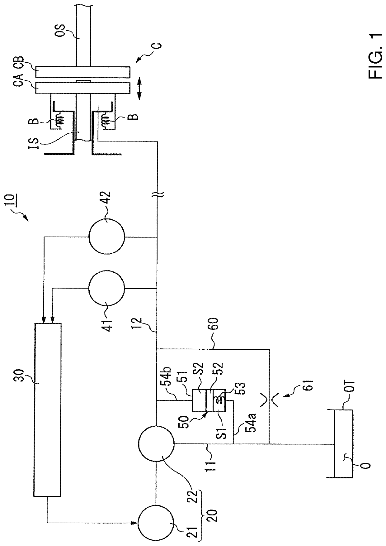
[0012]As shown in FIG. 1, a clutch control device 10 of the present embodiment controls a hydraulic clutch C. The hydraulic clutch C switches connection and disconnection between a driving shaft IS and a driven shaft OS. FIG. 1 shows a state in which the driving shaft IS and the driven shaft OS are disconnected. The driving shaft IS and the driven shaft OS are coaxial with each other. In the following description, the direction parallel to a central axis of the driving shaft IS and a central axis of the driven shaft OS (the left to right direction in FIG. 1) may be simply referred to as an “axial direction.” The hydraulic clutch C is mounted, for example, in a vehicle.

[0013]A first clutch plate CA is fixed to the driving shaft IS. A second clutch plate CB is fixed to the driven shaft OS. The first clutch plate CA and the second clutch plate CB are arranged to face each other. The driving shaft IS and the first clutch plate CA are arranged movably in the axial direction. A force is a...


PUM


Abstract

A clutch control device includes a pump to feed oil to a hydraulic clutch, an input side oil passage connecting an oil tank and the pump and through which oil sucked from the oil tank to the pump passes, and an output side oil passage connecting the pump and the hydraulic clutch and through which oil that is pressurized by the pump and is fed from the pump to the hydraulic clutch passes. A damper connected to the input side oil passage and the output side oil passage includes an oil container containing oil, a partition that partitions the oil container into first and second spaces along a predetermined direction and at least a portion of which is movable in the predetermined direction, a first connection oil passage connecting the first space and the input side oil passage, a second connection oil passage connecting the second space and the output side oil passage, and an elastic portion that applies a force to the partition to move the partition toward the second space in the predetermined direction. The first and second spaces are filled with oil.

Description

BACKGROUND OF THE INVENTION1. Field of the Invention[0001]The present invention relates to a clutch control device.2. Description of the Related Art[0002]For example, Japanese Patent Laid-Open No. 2006-37991 discloses a lockup mechanism in which a substantially annular circumferential groove is provided in either a friction surface of a lockup clutch or an engagement surface of a front cover for the purpose of suppressing the occurrence of judder vibration.[0003]However, the judder vibration also occurs because the pressure of the oil fed to a hydraulic clutch using a pump fluctuates and the force applied to the hydraulic clutch varies. In the configuration in which the circumferential groove is provided in the friction surface and the engagement surface as described above, there was a problem that it is impossible to suppress the judder vibration caused by the pressure fluctuation of the oil fed by the pump.SUMMARY OF THE INVENTION[0004]In view of the above problem, preferred embod...

Claims


Application Information

Patent Timeline
Patent Type & Authority Patents(United States)
IPC IPC(8): F16D48/02F15B1/02F15B15/02F15B15/20
CPCF16D25/14F15B1/021F15B15/02F15B15/20F16D48/02F16D2048/0215F15B1/02F16D25/12F16L55/05F16D2500/1026F16D2048/0257F16D48/066F16D2500/3024F16D25/0638F16D2048/0221
Inventor ETO, TAKAMITSUSAGARA, FUMIYA
Owner NIDEC TOSOK CORP
Why Eureka
Try Eureka