Actuator

a technology of actuators and actuators, applied in the field of actuators, can solve the problems of increasing the size and weight of actuators, insufficient driving force, and not allowing sufficient increase of the resonance frequency of the outer movable unit, so as to reduce the size and weight of the related rotatable components, reduce the rotational moments thereof, and reduce the effect of rotational driving for

Active Publication Date: 2020-08-27
NIPPON SIGNAL CO LTD
View PDF0 Cites 0 Cited by
  • Summary
  • Abstract
  • Description
  • Claims
  • Application Information

AI Technical Summary

Benefits of technology

[0008]The actuator includes the support that supports the driven unit, and the outer axis driver unit that is separate and independent from the support and is configured to rotate the support, in place of a conventional outer movable unit that has two functions to support the driven unit and to use the coil therein to rotate itself. This configuration allows providing a sufficient rotational driving force around the outer, second axis by reducing size and weight of the related rotatable components, and thus, by reducing rotational moments thereof, and also allows increasing the resonance frequency of the support. As such, the actuator provides a high-performance drive operation such as a raster scanning operation, for example.
[0009]According to a specific aspect of the present invention, the outer axis driver unit is a low-speed axis driver unit and the inner axis driver unit is a high-speed axis driver unit, so that the outer axis driver unit and the inner axis driver unit are configured to provide biaxial drive that causes the driven unit to perform raster scanning. This enables raster scanning with a simple drive control.
[0010]According to another aspect of the present invention, a plurality of outer axis driver units are provided. This provides an improved driving force performance for rotation around the second axis.
[0011]According to yet another aspect of the present invention, the outer axis driver units are a pair of outer axis driver units disposed at opposite ends of the support along the second axis. This enables transmitting driving forces for rotation around the second axis to the driven unit from both the opposite ends. Furthermore, providing a pair of outer axis driver units allows a more stabilized movement of the driven unit.
[0012]According to yet another aspect of the present invention, the inner axis driver unit includes a first coil unit configured to rotate around the first axis, and a first magnetic field applying unit configured to generate a magnetic field in a single direction so as to apply, to the first coil unit, a rotational force that rotates the first coil unit around the first axis, and the outer axis driver unit includes a second coil unit configured to rotate around the second axis. and a second magnetic field applying unit configured to generate a magnetic field in a single direction so as to apply, to the second coil unit, a rotational force that rotates the second coil unit around the second axis. This allows each of the magnetic field applying units to have a simple and small structure.
[0013]According to yet another aspect of the present invention, the natural frequency of the support is, higher than the torsional resonance frequency of the driven unit. This prevents or reduces the support from generating unwanted vibrations in the driven unit.

Problems solved by technology

However, the technique as disclosed in Patent Documents 1 and 2 requires each of the inner movable unit and the outer movable unit to have a driver coil, and thus tends to increase the size and weight of the actuator.
Accordingly, depending on the design of the actuator, the conventional technique may provide only an insufficient driving force for non-resonant drive operation from the outer movable unit, and may not permit sufficiently increasing the resonance frequency of the outer movable unit.
Thus, according to the conventional technique, it may be difficult to perform raster scanning operation, for example.
Furthermore, the conventional technique may allow generation of unwanted vibrations that may cause malfunction of the actuator, for example.
In addition, according to the conventional technique, distortion of the outer movable unit may adversely affect the operation of the actuator.

Method used


Image

  • Actuator
  • Actuator
  • Actuator

Examples


first embodiment

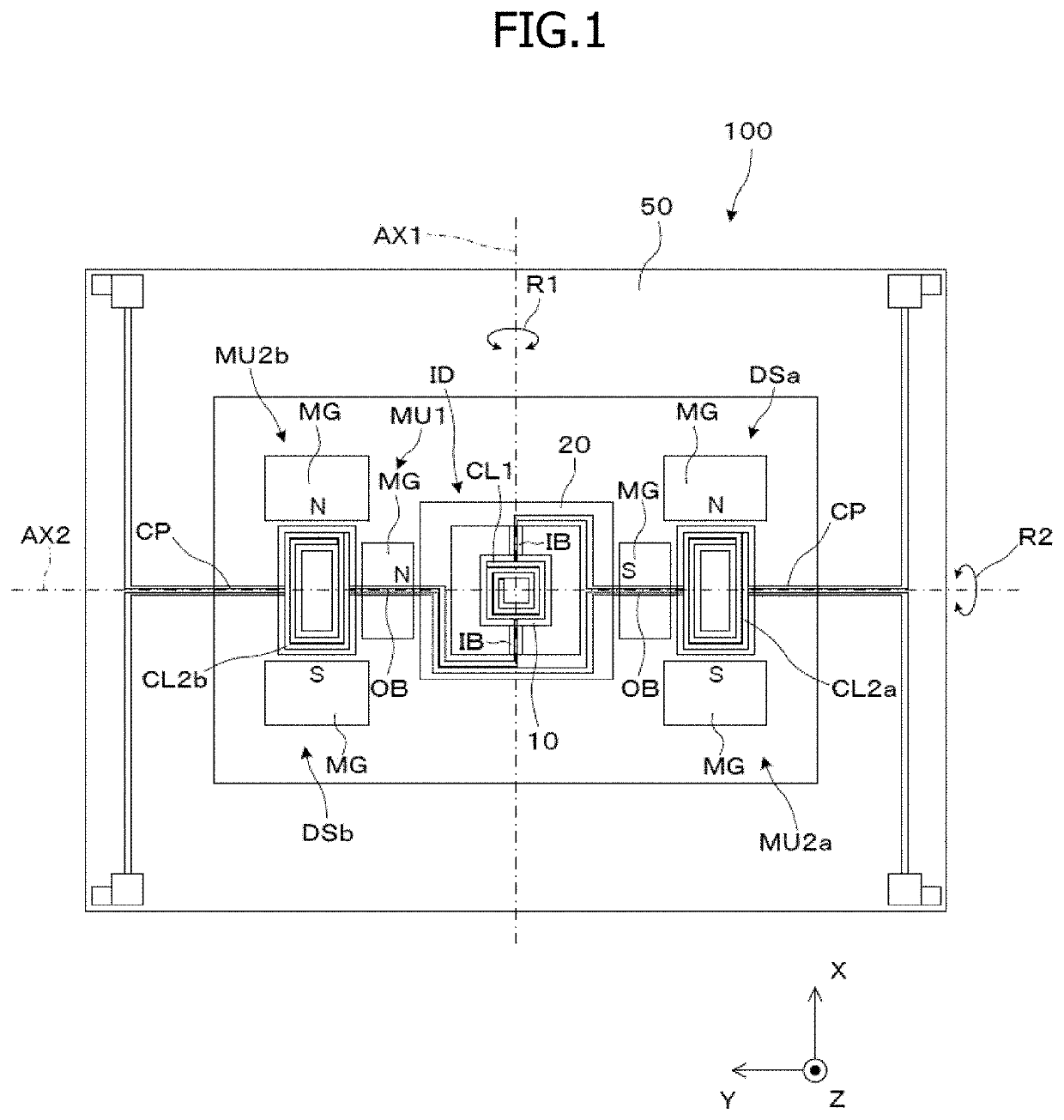
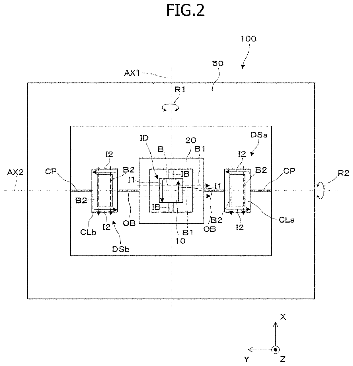
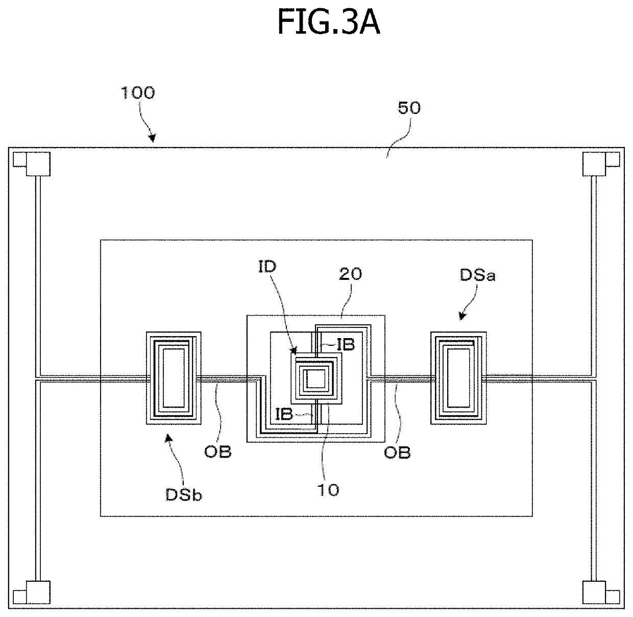
[0025]Hereinafter, an example of an actuator according to a first embodiment will be described with reference to FIG. 1 and other drawings. FIG. 1 is a block diagram for illustrating an example of the actuator according to this embodiment. An actuator 100 according to an aspect of this embodiment is applicable to an optical scanning device in a ranging image device, for example. The ranging image device is configured to scan an object with pulsed light such as laser pulses so as to acquire ranging image data of the object. Furthermore, the actuator 100 is also applicable to a display device configured to emit pulsed light synchronized in timing with optical scanning so as to project an image on a screen.

[0026]As shown in FIG. 1, the actuator 100 includes a driven unit 10, an inner axis driver unit ID, a support 20, a pair of outer axis driver units DSa, DSb, and a fixing unit 50, for example. The inner axis driver unit ID is configured to rotate the driven unit 10. The support 20 su...

second embodiment

[0061]Hereinafter, an example of an actuator according to a second embodiment will be described with reference to FIG. 7.

[0062]FIG. 7A is a diagram for illustrating an actuator 200 according to this embodiment. FIG. 7B is a schematic diagram of the actuator 200, showing only movable components thereof. As shown in FIGS. 7A and 7B, the actuator 200 according to this embodiment is a modification of the actuator 100 according to the first embodiment, and includes the same components as the actuator 100, except for the outer axis driver unit. Thus, the same reference numerals are given to the same components as those in the first embodiment, and detailed description thereof will be omitted below.

[0063]As shown in FIGS. 7A and 7B, the actuator 200 according to this embodiment includes a single outer axis driver unit DS, and differs in this regard from the actuator 100 exemplified in the aforementioned drawings including FIG. 1, which includes a pair of first and second outer axis driver ...


PUM


Abstract

An actuator according to the present invention includes a support 20 that supports a driven unit 10, and outer axis driver units DSa, DSb that are separate and independent from the support 20 and configured to rotate the support 20. This configuration allows providing a sufficient rotational driving force around the outer, second axis AX2 by reducing size and weight of the related rotatable components and thus by reducing rotational moments thereof, and also allows increasing the resonance frequency of the support 20. As such, the actuator according to this embodiment provides a high-performance drive operation such as a raster scanning operation, for example.

Description

TECHNICAL FIELD[0001]The present invention relates to an actuator that may be used as a driving actuator for a micro-electro-mechanical system (MEMS) device, for example.BACKGROUND ART[0002]A known example of driving actuators for MEMS devices is configured to provide biaxial drive to rotate a driven unit, such as a mirror, and includes an inner movable unit including a driver coil and the driven unit, and an outer movable unit including a driver coil and disposed so as to surround the inner movable unit (see Patent Documents 1 and 2).[0003]However, the technique as disclosed in Patent Documents 1 and 2 requires each of the inner movable unit and the outer movable unit to have a driver coil, and thus tends to increase the size and weight of the actuator. This tendency is particularly evident in the outer movable unit for low-speed axis drive, since the outer movable unit is configured both to support the inner movable unit and to use the driver coil therein to rotate itself. Accordi...

Claims


Application Information

Patent Timeline
Patent Type & Authority Applications(United States)
IPC IPC(8): G02B26/08H02K33/18G02B26/10
CPCG02B26/085G02B26/101H02K33/18B81B3/00G02B26/105
Inventor TOSA, HIROSHI
Owner NIPPON SIGNAL CO LTD
Why Eureka
Try Eureka