Fuel pump

a fuel pump and pump body technology, applied in the direction of machines/engines, liquid fuel engines, positive displacement liquid engines, etc., can solve the problem of complex configuration of the fuel pump, and achieve the effect of simple configuration

Active Publication Date: 2019-01-15
TOYOTA JIDOSHA KK
View PDF25 Cites 0 Cited by
  • Summary
  • Abstract
  • Description
  • Claims
  • Application Information

AI Technical Summary

Benefits of technology

[0008]The present disclosure provides a fuel pump that moves a movable element connected to a plunger and a counterweight for the movable element in synchronization with each other with a simpler configuration.
[0009]A fuel pump includes a first pump unit, a first movable element, a second movable element, an electromagnet, a magnetic member and a first spring. The first pump unit includes a first cylinder, a first plunger that reciprocates inside the first cylinder, and a first pressurizing chamber defined by the first cylinder and the first plunger. The first pump unit is configured to pressurize fuel inside the first pressurizing chamber by moving the first plunger inside the cylinder. The first movable element is connected to the first plunger. The second movable element is provided so as to face the first movable element in a direction in which the first plunger moves. The second movable element is configured to function as a counterweight for preventing or reducing vibrations that are created by reciprocation of the first movable element. The electromagnet is provided between the first movable element and the second movable element. The magnetic member is provided between the first movable element and the second movable element. The magnetic member is configured to attract both the first movable element and the second movable element when the electromagnet is energized. The first spring is configured to urge the first movable element and the second movable element so as to move away from each other.
[0014]A distance between the first movable element and the magnetic member and a distance between the second movable element and the magnetic member change in response to an energization state of the electromagnet. When a change in the distance between each movable element and the magnetic member is regarded as an actuated amount of the movable element, if there occurs a difference between the actuated amounts of the movable elements in process in which the movable elements are attracted by the magnetic member or in process in which the movable elements move away from the magnetic member, the period of the reciprocation of the first movable element and the period of the reciprocation of the second movable element deviate from each other. As a result, the effect of preventing or reducing vibrations of the first movable element by using the reciprocation of the second movable element decreases.
[0015]In this respect, with the above configuration, when there is a difference between a deflection amount of the second spring and a deflection amount of the third spring due to a difference in actuated amount between the movable elements, there occurs a difference between the urging force of the second spring, which acts on the first movable element, and the urging force of the third spring, which acts on the second movable element. The first movable element and the second movable element are urged by one of the springs, having a larger urging force, due to such a difference in urging force, so the distance between the first movable element and the magnetic member and the distance between the second movable element and the magnetic member both change, and a difference between the actuated amounts of the movable elements reduces.
[0016]For example, when the distance between the first movable element and the magnetic member is longer than the distance between the second movable element and the magnetic member and the deflection amount of the second spring is larger than the deflection amount of the third spring, the urging force of the second spring, which acts on the first movable element, is larger than the urging force of the third spring, which acts on the second movable element. Therefore, the first movable element is urged by the urging force of the second spring in a direction in which the first movable element approaches the magnetic member, while the second movable element is urged in a direction in which the second movable element moves away from the magnetic member. In this way, when the distance between the first movable element and the magnetic member is longer than the distance between the second movable element and the magnetic member, the first movable element is pressed in a direction in which the first movable element approaches the magnetic member, and the second movable element is pressed in a direction in which the second movable element moves away from the magnetic member, so a difference in actuated amount between the first movable element and the second movable element reduces.
[0017]In this way, with the above configuration, it is possible to reduce a difference in actuated amount between the movable elements, so it is possible to prevent a deviation between the period of the reciprocation of the first movable element and the period of the reciprocation of the second movable element.

Problems solved by technology

However, in order to synchronize the motion of the counterweight with the reciprocation of the plunger, an actuating mechanism that reciprocates the counterweight, a controller for controlling the reciprocation of the counterweight, and the like, are additionally required, with the result that the configuration of the fuel pump becomes complex.

Method used


Image

  • Fuel pump
  • Fuel pump
  • Fuel pump

Examples


Embodiment Construction

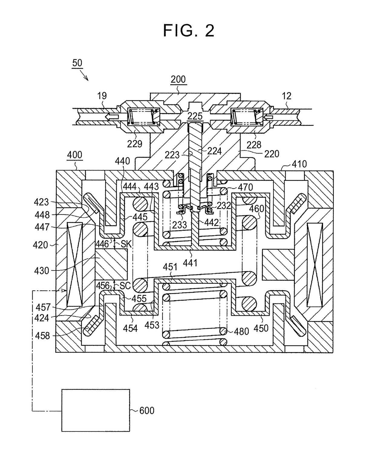
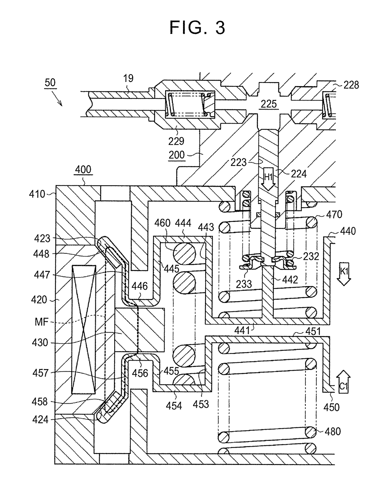
[0030]Hereinafter, a fuel pump according to an embodiment will be described in detail with reference to FIG. 1 to FIG. 6. The fuel pump 50 according to the present embodiment is configured as a high-pressure fuel pump that is provided in a vehicle-mounted direct injection engine.

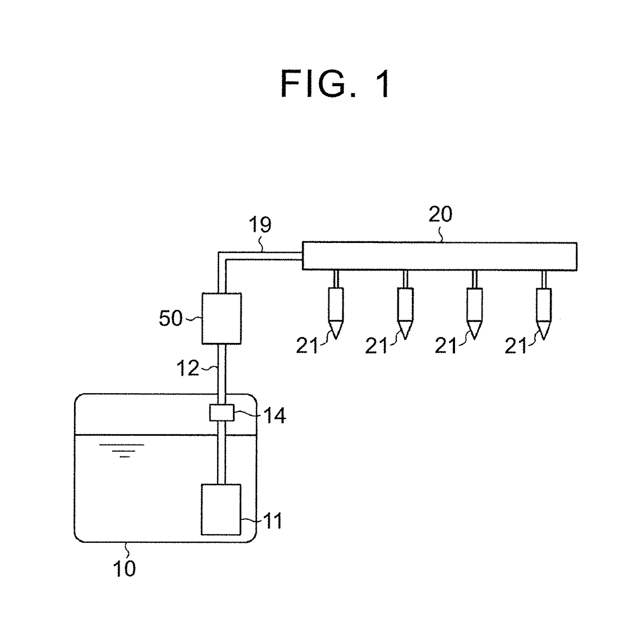
[0031]As shown in FIG. 1, a feed pump 11 that draws fuel is provided inside the fuel tank 10 of the direct injection engine. The feed pump 11 is connected to the fuel pump 50 via a low-pressure fuel passage 12. A regulator 14 is provided in the low-pressure fuel passage 12. The regulator 14 drains fuel inside the low-pressure fuel passage 12 to the fuel tank 10 when a fuel pressure inside the low-pressure fuel passage 12 exceeds a prescribed value.

[0032]The fuel pump 50 is, for example, provided near the fuel tank, and is connected to a delivery pipe 20 via a high-pressure fuel passage 19. Injectors 21 are connected to the delivery pipe 20. The injectors 21 are respectively provided in correspondence with cy...


PUM


Abstract

A fuel pump includes a plunger that reciprocates inside a cylinder. The fuel pump includes a first movable element connected to the plunger, a second movable element that functions as a counterweight for preventing or reducing vibrations that are created by reciprocation of the first movable element, an electromagnet provided between the first movable element and the second movable element, a magnetic member that is provided between the first movable element and the second movable element and that attracts both the first movable element and the second movable element when the electromagnet is energized, and a first spring that urges the first movable element and the second movable element so as to move away from each other.

Description

CROSS-REFERENCE TO RELATED APPLICATIONS[0001]The present disclosure claims priority to Japanese Patent Application No. 2015-179692 filed on Sep. 11, 2015, which is incorporated herein by reference in its entirety including the specification, drawings and abstract.BACKGROUND[0002]1. Technical Field[0003]The present disclosure relates to a fuel pump.[0004]2. Description of Related Art[0005]There is known a fuel pump that pressurizes fuel in a pressurizing chamber defined by a cylinder and a plunger by the movement of the plunger inside the cylinder. An actuating mechanism for reciprocating such a plunger is, for example, the device described in Japanese Patent Application Publication No. 2014-117149 (JP 2014-117149 A). The device includes a movable element that reciprocates by an electromagnet. In the device, a piston that functions as a plunger is connected to the movable element.[0006]Incidentally, as the movable element is reciprocated, vibrations are created by the reciprocation. ...

Claims


Application Information

Patent Timeline
Patent Type & Authority Patents(United States)
IPC IPC(8): F02M37/04F02M59/02F04B53/16F04B53/14F04B23/06F04B19/22
CPCF02M59/025F04B53/16F04B23/06F04B53/14F04B19/22F02M37/04F04B17/042F04B49/06F04B49/12F04B53/001
Inventor ASAYAMA, KAZUHIRO
Owner TOYOTA JIDOSHA KK
Why Eureka
Try Eureka