

Ellipsometer
a technology of ellipsometer and ellipsometer, which is applied in the field of imaging ellipsometer, can solve the problems of inability to precisely focus light on a minute pattern, inability to precisely measure the minute pattern, and thin film can affect the device, etc., and achieve the effect of improving the auto-focus function
- Summary
- Abstract
- Description
- Claims
- Application Information
AI Technical Summary
Benefits of technology
Problems solved by technology
Method used
Image

Examples
Embodiment Construction
[0033]Exemplary embodiments of the present disclosure may have various modifications and embodiments, and certain embodiments will be illustrated in the drawings and described in detail in the detailed description. The effects, characteristics, and methods of achieving the effects and the characteristics of the present disclosure will be made clear with reference to the embodiments described below in detail with reference to the drawings. However, the present disclosure is not limited to the embodiments described hereinafter, and may be realized as various embodiments.
[0034]It will be understood that when a layer, region, or component is referred to as being “formed on,” another layer, region, or component, it can be directly or indirectly formed on the other layer, region, or component.
[0035]Sizes of elements in the drawings may be exaggerated for convenience of explanation.
[0036]Hereinafter, exemplary embodiments of the present disclosure will be described in detail with reference...
PUM
| Property | Measurement | Unit |
|---|---|---|
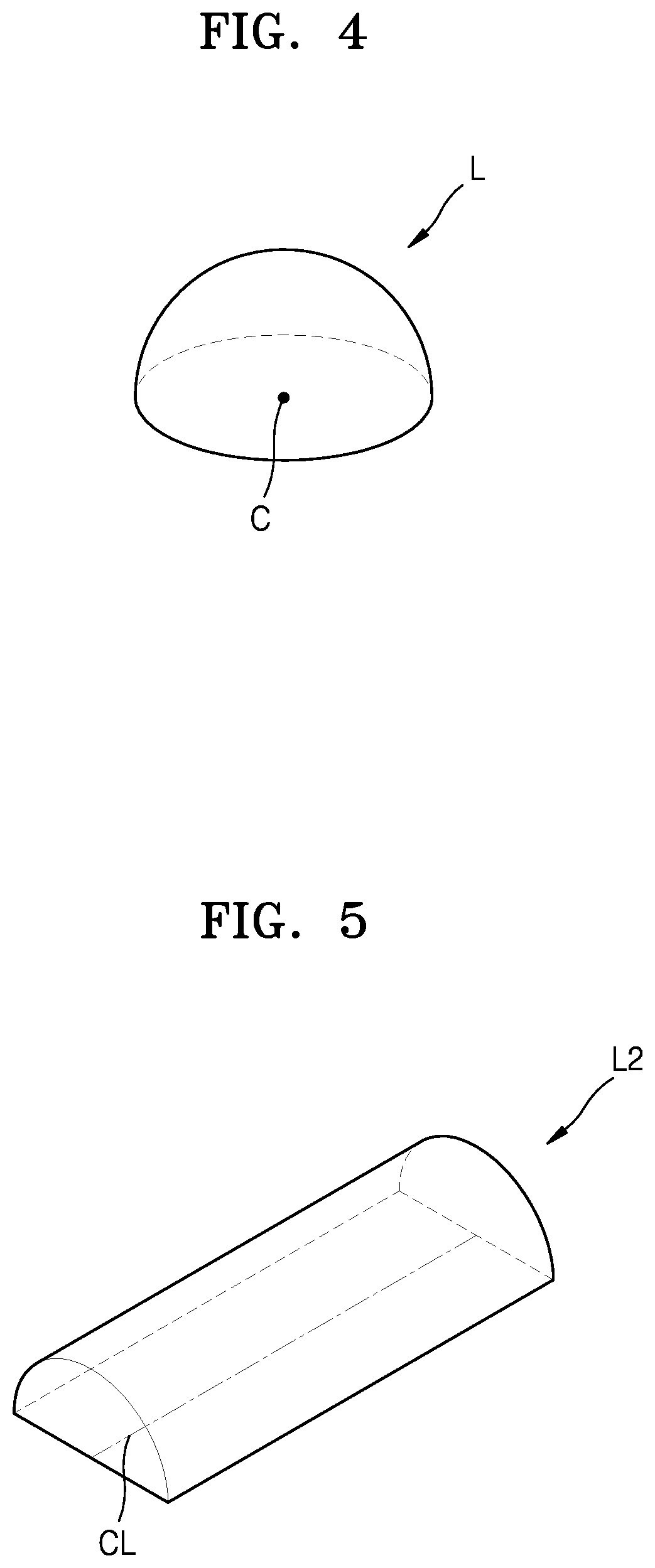
| semi-spherical shape | aaaaa | aaaaa |
| semi-cylindrical shape | aaaaa | aaaaa |
| charge | aaaaa | aaaaa |
Abstract
Description
Claims
Application Information