
Enclosure for protecting electrical components, cables and the like

a technology for enclosures and electrical components, applied in the direction of screws, nuts, sheets, etc., can solve the problems of increasing the risk of water ingress, affecting reducing so as to improve the waterproofing effect of the enclosur

Active Publication Date: 2021-04-06
ELECTRIX INT
View PDF12 Cites 0 Cited by
  • Summary
  • Abstract
  • Description
  • Claims
  • Application Information

AI Technical Summary

Benefits of technology

The invention is a sealed enclosure that prevents water ingress through the use of a spacer with internally threaded portions and a retaining member with a threaded portion. A cap with internally threaded portions ensures that water cannot enter the enclosure. The use of a third threaded portion simplifies the installation process and allows for one-man operation. The seal between the spacer and the apertured face further improves the waterproofing of the enclosure. This is important because a portion of the installation process involves creating apertures in the rear face of the enclosure, and the precise size of these apertures is outside of the manufacturer's control.

Problems solved by technology

The inclusion of the mounting apertures in the rear wall of the enclosure represents a risk of water ingress.
This can be reasonably effective but becomes completely ineffective if the screw becomes loose or is not correctly fixed to the wall to apply sufficient pressure on the washer to create the seal.
However, such legs can increase the risk of water ingress by increasing the number of junctions that needs sealing.
Although nylon washers can be used to seal between the fixing screw and the rear wall of the enclosure the danger of the integrity of the screw mounting to the wall is increased by the inclusion of the legs.
Furthermore, the longer the legs the greater the risk that an impact force against the enclosure will loosen the fixing screw from the wall.
It is also the case that mounting the device with legs can prove difficult as each leg must be held in position whilst being installed.
This often results in the installation process becoming a two-person job.

Method used


Image

  • Enclosure for protecting electrical components, cables and the like
  • Enclosure for protecting electrical components, cables and the like
  • Enclosure for protecting electrical components, cables and the like

Examples


Embodiment Construction

[0024]The following description of the preferred embodiment(s) is merely exemplary in nature and is in no way intended to limit the invention, its application, or uses.

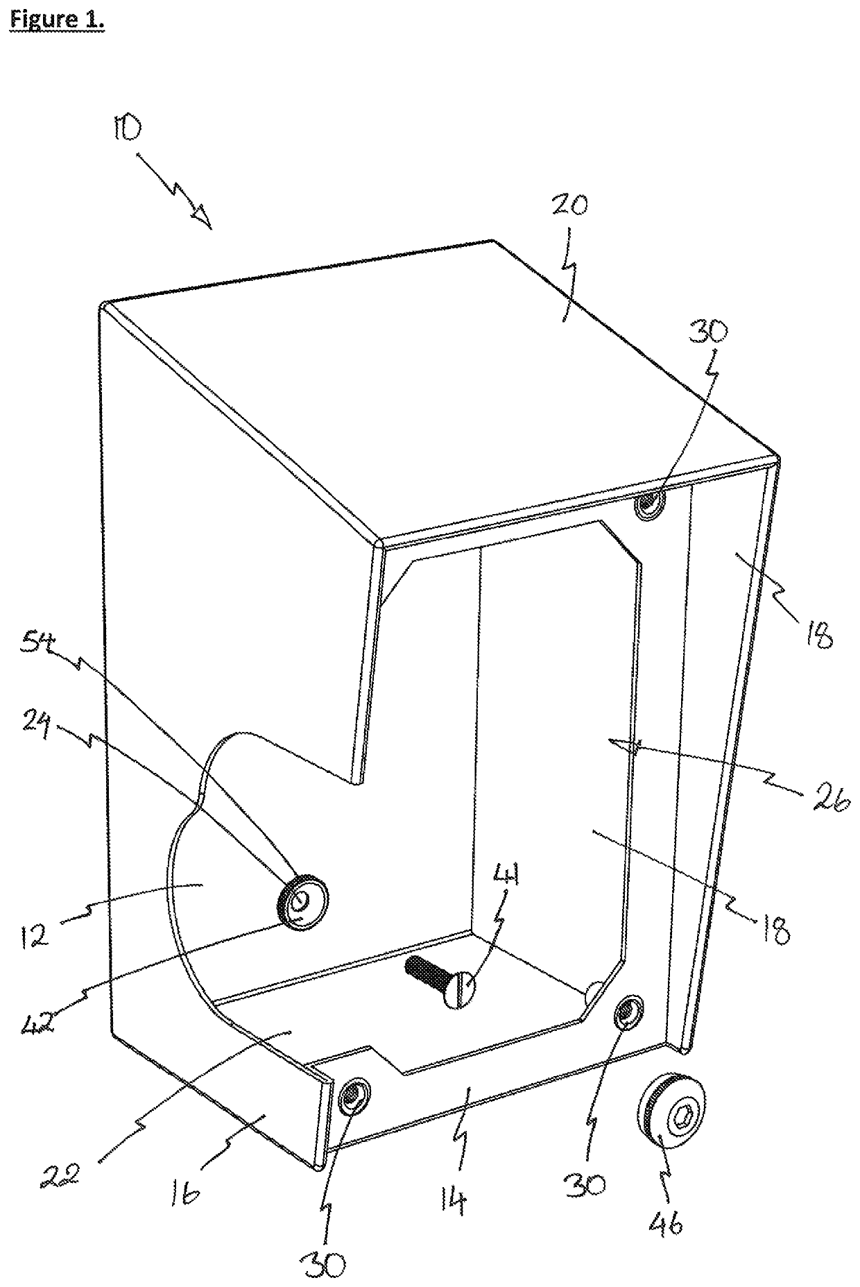
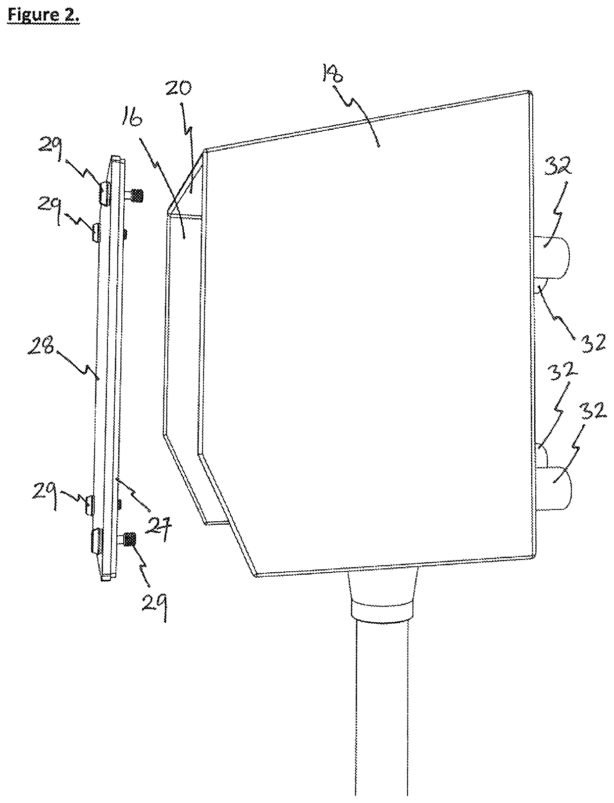
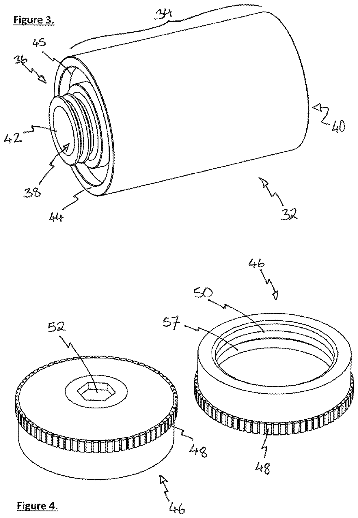
[0025]An enclosure 10 is shown in FIGS. 1 and 2 and some components are shown in more detail in FIGS. 3 to 6. The enclosure 10 is formed from a plurality, specifically six, stainless steel faces 12, 14, 16, 18, 20, 22 which together form an approximately cuboid shaped body and define a volume in which electrical components can be placed and / or into which electrical cables can be run (although none of these components or cables are shown in the figures). The rearmost face 12, which in use is located adjacent the surface onto which the enclosure will be mounted, is provided with a plurality of apertures (indicated at 24) which extend through this rear face of the cuboid. These apertures are either produced during manufacture of the enclosure or created by an installer on site as part of the installation process.

[0026]Th...


PUM


Abstract

An enclosure for protecting electrical components, cables and the like. The enclosure has a plurality of faces which define a volume with an opening to provide access. One face has apertures for receiving fixing screws to fix the enclosure to a wall or surface. There is a lid to close the opening. Spacer members separate the enclosure from the surface. Each has a bore extending through it and a threaded portion extending from a surface of the face which engages the apertured face of the enclosure. For each spacer there is a cap for covering the aperture and sealing the apertured face. Also provided for each spacer is a retainer for threading onto the externally threaded portions when the spacer's threaded portion extend through the apertured face.

Description

CROSS-REFERENCE TO RELATED APPLICATIONS[0001]The application claims priority under 35 U.S.C. § 119 of GB Application No. 1805475.9 filed Apr. 3, 2018. The disclosure of the above application is incorporated herein by reference.FIELD OF INVENTION[0002]The present invention relates to an enclosure for protecting electrical components, cables and the like and relates particularly, but not exclusively, to a wall mounted enclosure which is spaced from the wall allowing easy access for cleaning the surface onto which the enclosure is mounted.BACKGROUND[0003]It is commonplace for enclosures to be used to protect electrical components, the cables which connect them as well as the junctions between the components in the cables. Typically, such an enclosure is mounted to a surface, such as a wall, using mounting screws which extend through apertures in the rearmost surface of the enclosure and into the wall. One of the most important protections that the enclosure provides is against water in...

Claims


Application Information

Patent Timeline
Patent Type & Authority Patents(United States)
IPC IPC(8): H02G3/08F16B37/14H02G3/10H02B1/28F16B33/00H02B1/40
CPCH02G3/081F16B33/004F16B37/145H02B1/28H02B1/40H02G3/088H02G3/10F16B19/02F16B39/14F16B5/065F16B5/0258H05K5/0073H05K5/0204H05K5/0234
Inventor THOMPSON, CHRISTOPHER
Owner ELECTRIX INT
Learn More