
Modular pedicle screw with multi-part cam lock structure

a pedicle screw and cam lock technology, applied in the field of spine screw assemblies, can solve the problems of deficiency in many respects of the prior art assembled fixed angle spine rod pedicle screw, and achieve the effect of increasing and decreasing the size of the opening

Active Publication Date: 2021-04-13
LIFE SPINE INC
View PDF9 Cites 0 Cited by
  • Summary
  • Abstract
  • Description
  • Claims
  • Application Information

AI Technical Summary

Benefits of technology

The patent describes a modular pedicle screw assembly that can capture and release the ball of a threaded shank through rotation of closures. The closure geometry interacts with the internal chamber of the head to selectively change the size of an opening. The assembly can transition between an open state and a closed state to secure the shank in the head or to prevent disassembly. The transition between states is reversible. The technical effect of this invention is to provide a reliable and secure mechanism for attaching a threaded shank to a spine rod holder during spine surgery.

Problems solved by technology

However, the prior art assembled fixed angle spine rod pedicle screws are deficient in many respects.

Method used


Image

  • Modular pedicle screw with multi-part cam lock structure
  • Modular pedicle screw with multi-part cam lock structure
  • Modular pedicle screw with multi-part cam lock structure

Examples


Embodiment Construction

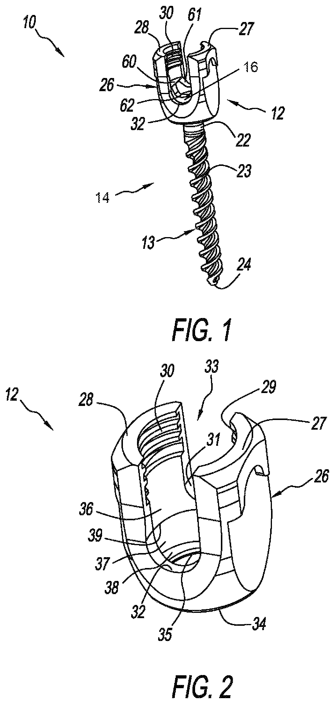
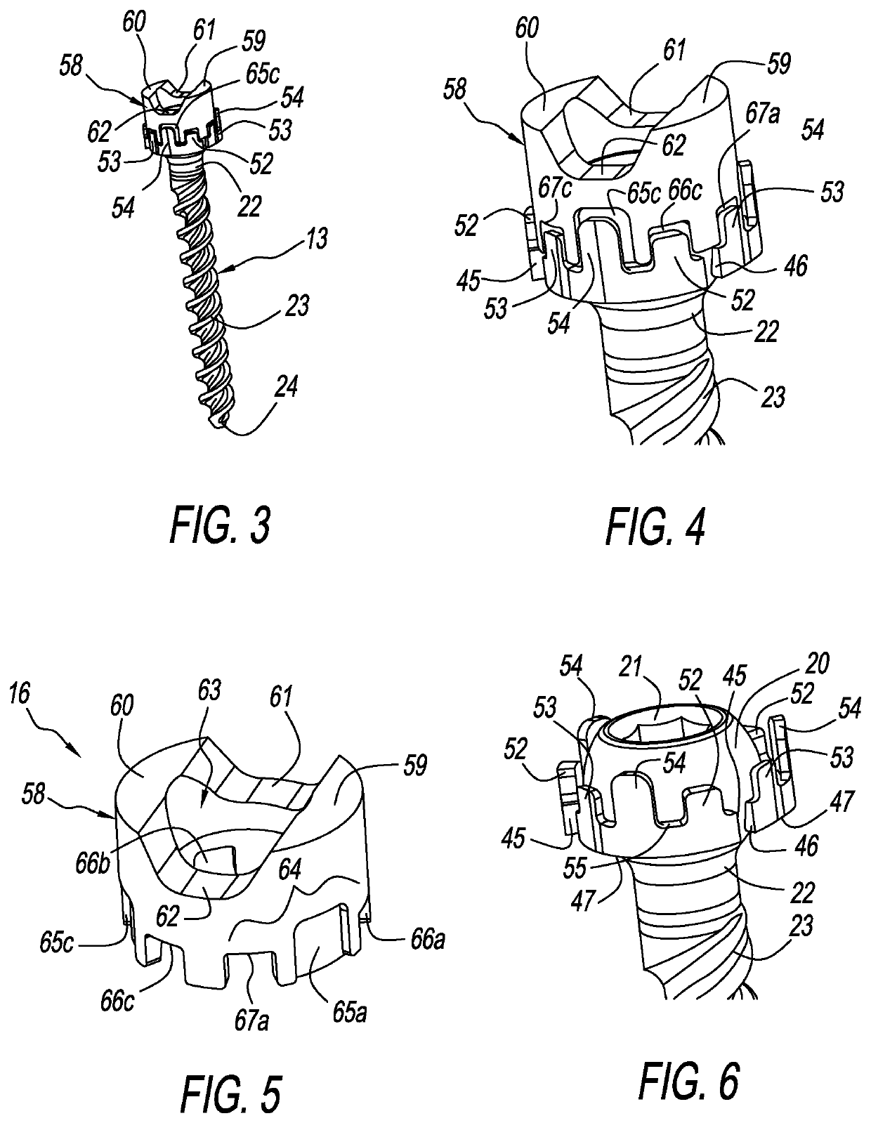
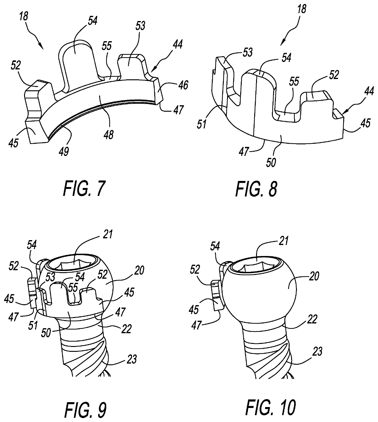
[0062]Referring to FIG. 1, there is depicted a pedicle screw assembly (or simply pedicle screw), generally designated 10, comprising a shank or screw 14 and a subassembly consisting of a head 12, one or more closures 18 (not seen in FIG. 1, see e.g., FIGS. 7, 8 and 13) and a ring 16, all fashioned in accordance with the present principles. The pedicle screw assembly 10 may be considered a modular pedicle screw assembly since it consists of the various components shown and described herein. FIGS. 2-36 depict views of the various components of the present pedicle screw assembly 10 as well as subassemblies and illustrative depictions thereof.

[0063]The head 12, as particularly shown in FIGS. 2 and 15, is characterized by a generally tulip-shaped body 26 configured to receive and retain a spine rod (not shown), and be received onto the shank 14 in the manner described herein. The body 26 has an axial bore 33 from a top of the body 26 to a bottom 34 of the body 26 that defines a first cur...


PUM


Abstract

A modular pedicle screw assembly has a multi-part cam lock structure for fixing a threaded shank to a head subassembly. A modular pedicle screw assembly provides capture and release of a spherical end of a threaded shank by a head through rotation of closures radially disposed in an internal chamber of the head. Geometry of the closures cooperate with geometry of the internal chamber, providing a selective cam action between the closures and the internal chamber to increase and decrease size of an opening formed by the closures. Closure rotation produces an open state where the spherical end of the threaded shank can pass through the closures, releasing the spherical end of the threaded shank from the head, and a closed state where the spherical end of the threaded shank cannot pass through the closures thereby capturing the spherical end of the threaded shank in the head.

Description

CROSS-REFERENCE TO RELATED APPLICATIONS[0001]This U.S. non-provisional patent application claims the benefit of and / or priority under 35 U.S.C. § 119(e) to U.S. provisional patent application Ser. No. 62 / 651,390 filed Apr. 1, 2018 titled “Modular Pedicle Screw Allowing Repeated Assembly and Disassembly” the entire contents of which is specifically incorporated herein by reference.FIELD OF THE INVENTION[0002]The present invention relates to spine screw assemblies for spine fixation and, more particularly, to modular pedicle screw assemblies for spine rod applications.BACKGROUND OF THE INVENTION[0003]Many people contend with orthopedic issues as a result of age, disease and trauma, as well as congenital and acquired complications and conditions. While some of these conditions can be alleviated without surgery, other conditions require a surgical procedure. In some cases, the surgical procedure may include the insertion of an orthopedic implant. Orthopedic spine assemblies and construc...

Claims


Application Information

Patent Timeline
Patent Type & Authority Patents(United States)
IPC IPC(8): A61B17/70A61B17/86
CPCA61B17/7032A61B17/7037A61B17/8605
Inventor SAMUEL, FORRESTPALAGI, GREGORY
Owner LIFE SPINE INC
Learn More