Welding apparatus

a welding electrode and electrode tip technology, applied in the direction of welding apparatus, manufacturing tools, welding/cutting media/materials, etc., can solve the problems of consuming copper alloy, limited life of the welding electrode, and not being able to weld nuts in the wrong location or upside down, etc., to achieve a higher melting point and high melting point

Active Publication Date: 2021-04-13
HUYS IND LTD
View PDF50 Cites 0 Cited by
  • Summary
  • Abstract
  • Description
  • Claims
  • Application Information

AI Technical Summary

Problems solved by technology

The head of the welding electrode has a limited life, for many reasons.
Typically the electrode tip is made of a copper alloy and is consumed over time, as the repeated heating and cooling of the tip degrades the tip.
Especially where the nuts and studs are fed to the welding electrode heads automatically, it is not desirable to weld the nuts in the wrong location or upside down.

Method used


Image

  • Welding apparatus
  • Welding apparatus
  • Welding apparatus

Examples


Embodiment Construction

[0024]The description that follows, and the embodiments described therein, are provided by way of illustration of an example, or examples, of particular embodiments incorporating one or more of the principles, aspects, and features of the present invention. These examples are provided for the purposes of explanation, and not of limitation, of those principles and of the invention. In the description, like parts are marked throughout the specification and the drawings with the same respective reference numerals. The drawings may be understood to be to scale and in proportion unless otherwise noted. The wording used herein is intended to include both singular and plural where such would be understood, and to include synonyms or analogous terminology to the terminology used, and to include equivalents thereof in English or in any language into which this specification many be translated, without being limited to specific words or phrases.

[0025]The scope of the invention herein is defin...


PUM

PropertyMeasurementUnit
electrical discharge currentsaaaaaaaaaa
electrically conductiveaaaaaaaaaa
melting pointaaaaaaaaaa

Abstract

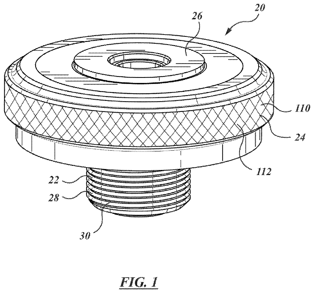
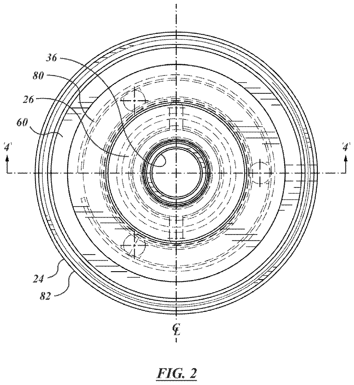
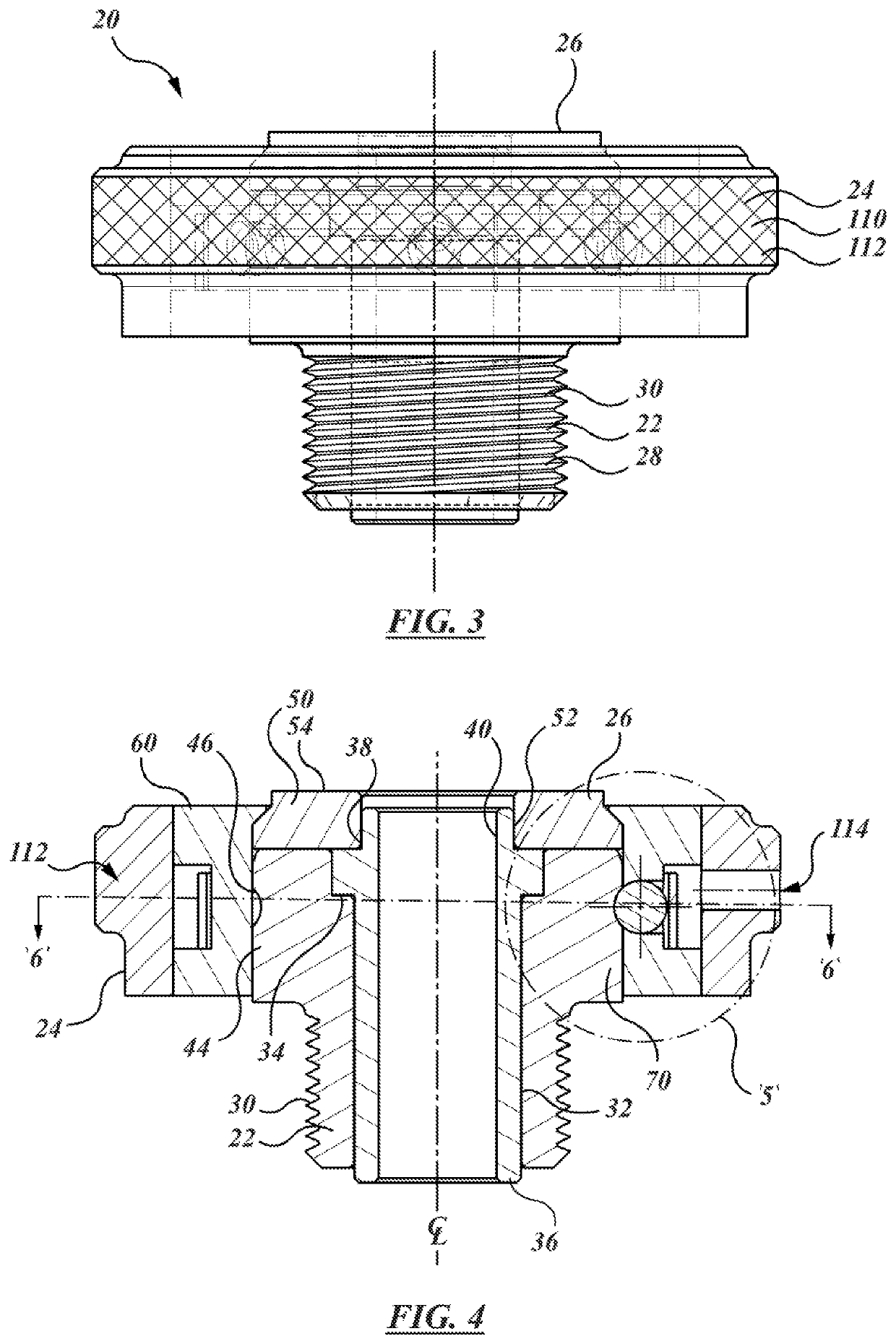
A welding electrode apparatus has a base member and a locking ring for clamping a consumable electrode tip to the electrode base. The base and the tip are predominantly made of copper, or a copper alloy. The base member has a first end that is threaded to fit a welding head that supplies electric current; and an electrically conductive second end to which the electrode tip is mounted. The second portion has an externally facing, axially extending cylindrical wall. A circumferential groove is formed in the wall. The locking ring has a quick-disconnect feature in the form of an array of spring-loaded stainless steel ball bearing detents that deflect to ride upon the cylindrical wall, and spring inwardly to seat in the circumferential groove.

Description

CROSS-REFERENCE TO RELATED APPLICATIONS[0001]This application claims priority to and the benefit of U.S. Provisional Patent Application Ser. No. 62 / 353,189, filed Jun. 22, 2016, the disclosures of which are incorporated herein in their entirety by reference.FIELD OF THE INVENTION[0002]This invention relates to the field of welding equipment.BACKGROUND OF THE INVENTION[0003]In automated processes, such as in the automotive industry, nuts and studs may be welded to body components, such as formed steel and aluminum alloy sheet members, prior to assembly. The nuts and studs are typically welded to the sheet at specified locations. The head of the welding electrode has a limited life, for many reasons. Typically the electrode tip is made of a copper alloy and is consumed over time, as the repeated heating and cooling of the tip degrades the tip. Especially where the nuts and studs are fed to the welding electrode heads automatically, it is not desirable to weld the nuts in the wrong loc...

Claims


Application Information

Patent Timeline
Patent Type & Authority Patents(United States)
IPC IPC(8): B23K9/28B23K11/00B23K35/02
CPCB23K9/282B23K11/0046B23K11/0053B23K35/0205
Inventor SCOTCHMER, NIGELREMENTER, FRANKLIN
Owner HUYS IND LTD
Why Eureka
Try Eureka