Redundant power supply system

a power supply system and redundancy technology, applied in emergency power supply arrangements, process and machine control, instruments, etc., can solve the problem of difficulty in swiftly supplying power from the battery to the power supply line, and achieve the effect of preventing overcharging

Active Publication Date: 2021-04-27
TOYOTA JIDOSHA KK
View PDF29 Cites 0 Cited by
  • Summary
  • Abstract
  • Description
  • Claims
  • Application Information

AI Technical Summary

Benefits of technology

[0005]The present invention has been made in view of the aforementioned problem, and an object of the present invention is to provide a redundant power supply system including a battery that can be prevented from being overcharged and that can be caused to swiftly function as a backup power supply for an important load when necessary.
[0007]In this redundant power supply system, on a path from the second DC-DC converter to the second battery, the first switching element and the first diode which performs rectification in the direction opposite to the path are provided, and, when the second battery is in the first state, the first switching element is turned off so that only a discharging path extending via the first diode is formed. By this control, the second battery in a fully charged state where the stored power amount thereof is equal to or larger than the first threshold value can be prevented from being overcharged, and the second battery can be caused to swiftly function as a backup power supply when necessary.
[0009]In this redundant power supply system, on the path from the second DC-DC converter to the second battery, the second switching element and the second diode which performs rectification in the direction of the path are provided, and, when the second battery is in the second state, the second switching element is turned off so that only a charging path extending via the second diode can be formed. By this control, the second battery having a stored power amount that is reduced to be equal to or smaller than the second threshold value can be prevented from being overdischarged.
[0011]With the redundant power supply system according to this mode, the discharge can be performed with use of the power storage section without being influenced by a charging action performed on the second battery by the second DC-DC converter, whereby the deterioration state of the second battery can be accurately determined.
[0013]With the redundant power supply system according to this mode, the discharge can be performed with use of the first battery without being influenced by the charging action performed on the second battery by the second DC-DC converter, whereby the deterioration state of the second battery can be more accurately determined.
[0016]The present invention can realize a redundant power supply system including a battery that can be prevented from being overcharged and that can be caused to swiftly function as a backup power supply for an important load when necessary.

Problems solved by technology

However, in this case, it becomes difficult to swiftly supply power from the battery to the power-supplying line when backup for the important load becomes necessary.

Method used


Image

  • Redundant power supply system
  • Redundant power supply system
  • Redundant power supply system

Examples


first embodiment

[0027][Configuration]

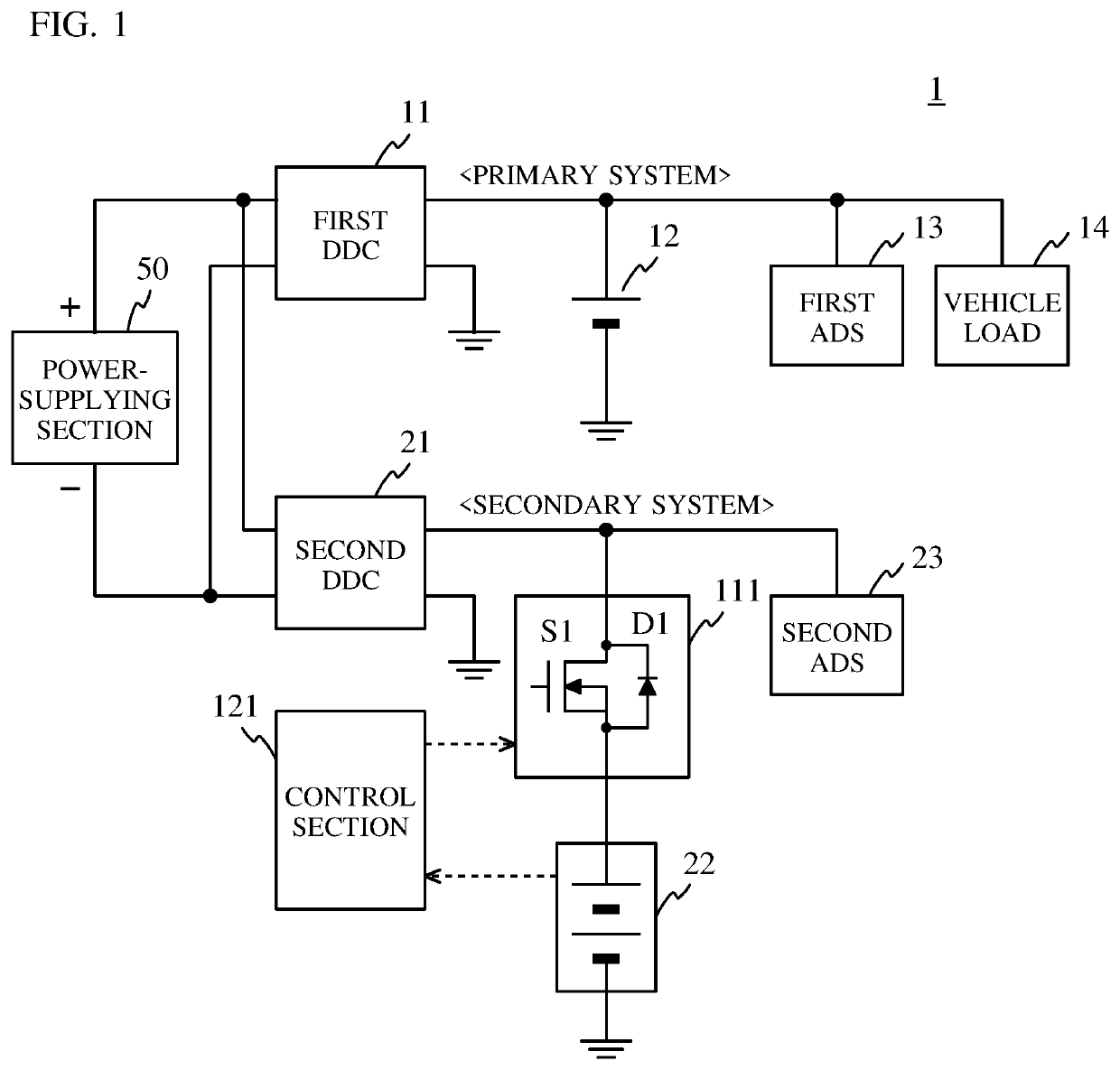
[0028]FIG. 1 is a block diagram indicating a schematic configuration of a redundant power supply system 1 according to a first embodiment of the present invention. The redundant power supply system 1 exemplified in FIG. 1 is composed of: a power supply device (primary system) including a first DC-DC converter (DDC) 11, a first battery 12, a first automatic driving system (ADS) 13, and a vehicle load 14; a power supply device (secondary system) including a second DC-DC converter (DDC) 21, a second battery 22, a second automatic driving system (ADS) 23, a battery protection circuit 111, and a control section 121; and a power-supplying section 50.

[0029]The redundant power supply system 1 is mounted to, for example, a vehicle capable of automatic driving by means of a device in the vehicle. In the redundant power supply system 1 mounted to the vehicle: during manual driving, the first battery 12 of the primary system is used for driving the vehicle; and, during auto...

second embodiment

[0048][Configuration]

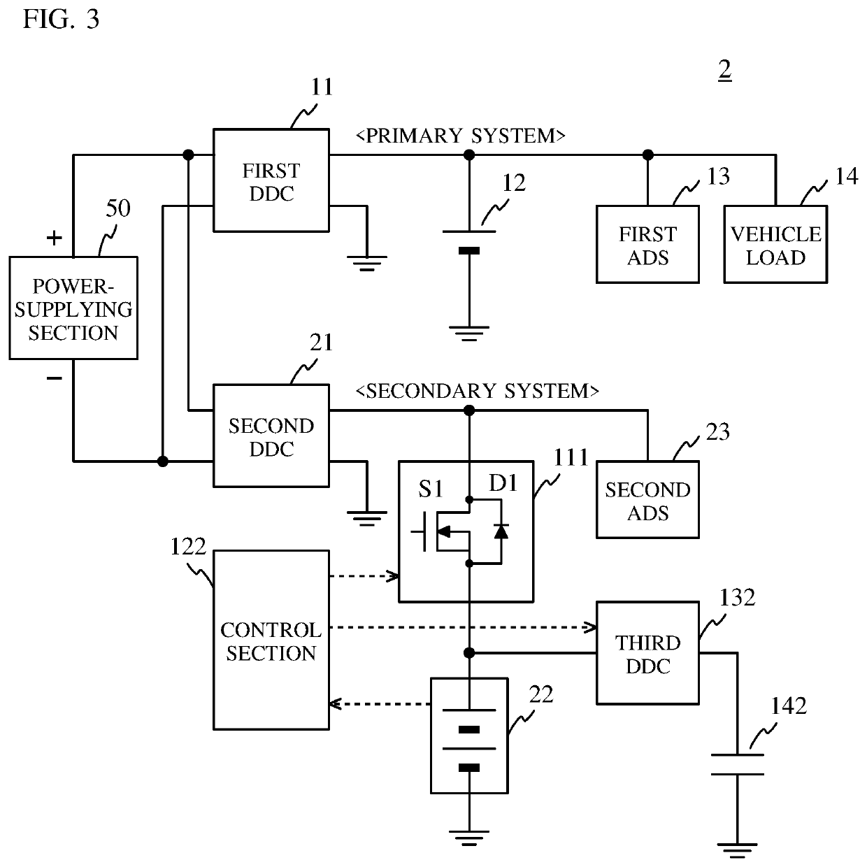
[0049]FIG. 3 is a block diagram indicating a schematic configuration of a redundant power supply system 2 according to a second embodiment of the present invention. The redundant power supply system 2 exemplified in FIG. 3 is different in configuration from the above-described redundant power supply system 1 according to the first embodiment in that a third DC-DC converter (DDC) 132 and a power storage section 142 are additionally provided and the control section 121 is replaced by a control section 122 different therefrom in control. The other components of the redundant power supply system 2 are identical to those of the above-described redundant power supply system 1. Thus, these components are denoted by the same reference characters, and the description thereof will be omitted.

[0050]The third DC-DC converter 132 is connected between the power storage section 142 and a connection point between the battery protection circuit 111 and the second battery 22. The...

third embodiment

[0060][Configuration]

[0061]FIG. 5 is a block diagram indicating a schematic configuration of a redundant power supply system 3 according to a third embodiment of the present invention. The redundant power supply system 3 exemplified in FIG. 5 is different in configuration from the above-described redundant power supply system 1 according to first embodiment in that the battery protection circuit 111 is replaced by a battery protection circuit 113 and the control section 121 is replaced by a control section 123. The other components of the redundant power supply system 3 are identical to those of the above-described redundant power supply system 1. Thus, these components are denoted by the same reference characters, and the description thereof will be omitted.

[0062]The battery protection circuit 113 is a relay circuit that is interposed between the second DC-DC converter 21 and the second battery 22, and that is for preventing the second battery 22 from being overcharged and overdisc...


PUM


Abstract

The redundant power supply system, in which a predetermined power is supplied via a first DC-DC converter (DDC) to a first battery and a first load of a primary system and the predetermined power is supplied via a second DDC to a second battery and a second load of a secondary system independent of the primary system, includes: a first switching element interposed between the second DDC and the second battery; a first diode which is connected in parallel to the first switching element and performs rectification in a direction from the second battery toward the second DDC; and a control section which turns off the first switching element when the second battery is in a first state where a stored power amount thereof is not smaller than a predetermined first threshold value, and turns on the first switching element when a state other than the first state is assumed.

Description

BACKGROUND OF THE INVENTIONField of the Invention[0001]The present invention relates to a redundant power supply system to be mounted to a vehicle.Description of the Background Art[0002]Patent document 1 (Japanese Laid-Open Patent Publication No. 2008-199763) discloses a power supply system which realizes a redundant configuration by being provided with: a first system and a second system in which power is supplied from a high-voltage power supply via DC-DC converters to a first battery and a second battery, respectively.[0003]In a power supply system with a redundant configuration, it is desired that deterioration of a battery of one of systems is suppressed through management, with high accuracy, of the power storage state of the battery when the battery is used as a backup power supply for an important load in automatic driving.[0004]Methods for suppressing the deterioration of a battery include a method in which the battery is prevented from being overcharged. A conceivable mean...

Claims


Application Information

Patent Timeline
Patent Type & Authority Patents(United States)
IPC IPC(8): H02J9/00H02J7/00H02M3/155
CPCH02J9/00H02J7/0021H02J7/0022H02M3/155H02J2007/0067H02J7/34H02J9/06H02J1/08H02J1/102B60R16/03H02J2310/40Y02T10/92H02J7/0025H02J7/0013
Inventor MATSUSHITA, NAOTO
Owner TOYOTA JIDOSHA KK
Why Eureka
Try Eureka