
Foldable electronic device

a technology of electronic devices and foldable parts, applied in the field of foldable electronic devices, can solve the problems of insufficient comfort and unsightly periphery of display screens, and achieve the effect of sufficient comfor

Active Publication Date: 2021-05-25
COMPAL ELECTRONICS INC
View PDF15 Cites 7 Cited by
  • Summary
  • Abstract
  • Description
  • Claims
  • Application Information

AI Technical Summary

Benefits of technology

The invention is a foldable electronic device that solves issues of large size, unsightly display screen, and discomfort during use. The device includes a pivot module, a linkage module, and an input module. The linkage module is connected to the pivot module and is driven by the pivot module to move the input module close to or away from the pivot module and to cause the input module to be inclined or parallel to the first body. The linkage module includes a first guide set, a second guide set, and a linkage set, which are all connected to the input module. The input module is movably disposed on the first body through the linkage set. The linkage set can be driven by the guide set or the pivot module to move the input module. The device is designed to be compact, comfortable, and have a unique input mechanism.

Problems solved by technology

Therefore, a person skilled in the art is to resolve problems that a current foldable electronic device has a relatively large volume, a periphery of a display screen is unsightly during use, and use comfort is insufficient.

Method used


Image

  • Foldable electronic device
  • Foldable electronic device
  • Foldable electronic device

Examples


Embodiment Construction

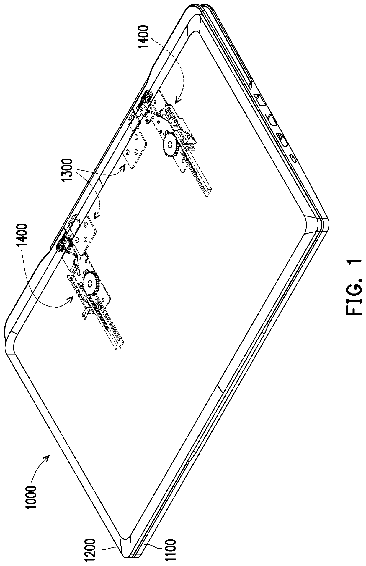
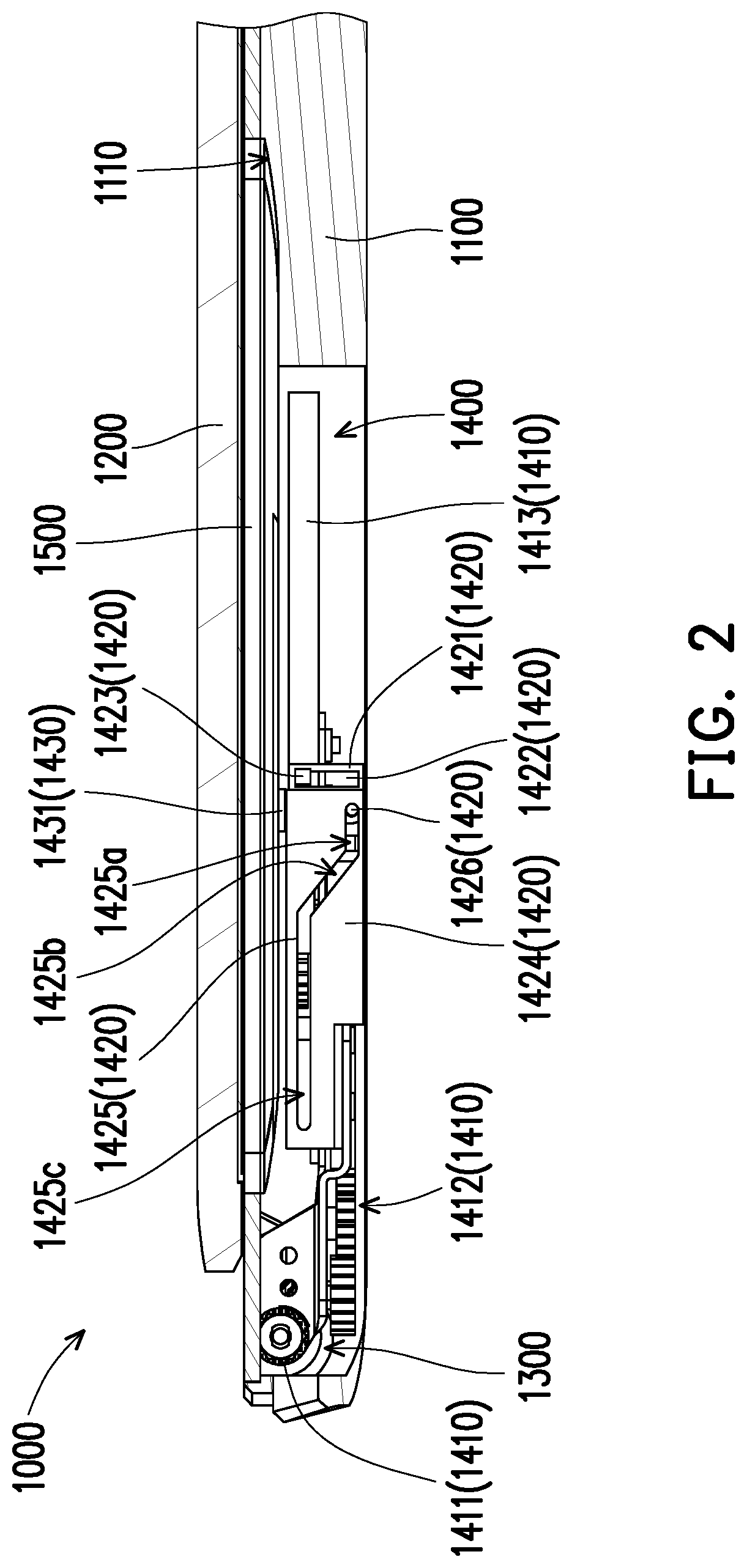
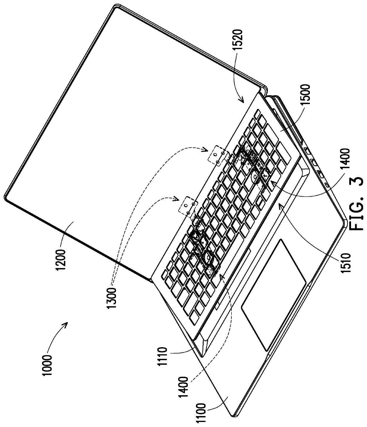
[0034]FIG. 1 is a schematic three-dimensional diagram of a foldable electronic device according to an embodiment of the invention. FIG. 2 is a schematic partial cross-sectional view of the foldable electronic device in FIG. 1. FIG. 3 is a schematic three-dimensional diagram in which a second body of the foldable electronic device in FIG. 1 is fully expanded relative to a first body. FIG. 4 is a schematic partial cross-sectional view of the foldable electronic device in FIG. 3. Referring to FIG. 1, FIG. 2, FIG. 3, and FIG. 4, a foldable electronic device 1000 includes a first body 1100, a second body 1200, a pivot module 1300, a linkage mechanism 1400, and an input module 1500. The pivot module 1300 is connected between the first body 1100 and the second body 1200, so that the second body 1200 is pivoted on the first body 1100 through the pivot module 1300, the second body 1200 can pivot relative to the first body 1100, and the second body 1200 can drive the pivot module 1300. The li...


PUM


Abstract

A foldable electronic device includes a first body, a second body, a pivot module, a linkage mechanism, and an input module. The pivot module is connected to the first body and the second body. The second body is pivoted on the first body through the pivot module. The linkage mechanism is disposed in the first body and is connected to the pivot module. The input module is movably disposed on the first body through the linkage mechanism. The linkage mechanism is configured to be driven by the pivot module to cause the input module to move to be close to or away from the pivot module and cause the input module to be inclined or parallel to the first body.

Description

CROSS-REFERENCE TO RELATED APPLICATION[0001]This application claims the priority benefit of U.S. provisional application Ser. No. 62 / 774,878, filed on Dec. 4, 2018. The entirety of the above-mentioned patent application is hereby incorporated by reference herein and made a part of this specification.BACKGROUND OF THE INVENTION1. Field of the Invention[0002]The invention relates to a foldable electronic device, and in particular, to a foldable electronic device having a liftable and slidable input module.2. Description of Related Art[0003]With the development of technologies, a foldable electronic device is commonplace in daily life. Generally, users of the foldable electronic device expect that the foldable electronic device is compact and portable and can provide a better viewing visual effect and better use comfort on the basis of being compact and portable. Therefore, a person skilled in the art is to resolve problems that a current foldable electronic device has a relatively lar...

Claims


Application Information

Patent Timeline
Patent Type & Authority Patents(United States)
IPC IPC(8): G06F1/16
CPCG06F1/1616G06F1/1624G06F1/1684G06F1/1667G06F1/1681G06F1/1666
Inventor LIN, CHE-HSIENCHU, CHE-HSIEN
Owner COMPAL ELECTRONICS INC
Learn More