Transmission line substrate and electronic device

a technology of transmission line substrate and electronic device, which is applied in the direction of insulated conductors, cables, waveguides, etc., can solve the problems of insufficient strength and durability of the transmission line substrate itself, and achieve the effects of reducing or preventing the separation of insulating base materials, mechanical strength and durability, and reducing or preventing irregularities

Active Publication Date: 2021-06-15
MURATA MFG CO LTD
View PDF36 Cites 1 Cited by
  • Summary
  • Abstract
  • Description
  • Claims
  • Application Information

AI Technical Summary

Benefits of technology

[0006]Preferred embodiments of the present invention provide transmission line substrates that achieve improved mechanical strength and durability against an external force and the like by significantly reducing or preventing separation of insulating base materials included in a stacked body from each other, in a structure in which the stacked body obtained by stacking a plurality of insulating base materials includes a plurality of transmission lines.

Problems solved by technology

As a result, the strength and durability of the transmission line substrate itself may be insufficient in some cases.

Method used


Image

  • Transmission line substrate and electronic device
  • Transmission line substrate and electronic device
  • Transmission line substrate and electronic device

Examples


first preferred embodiment

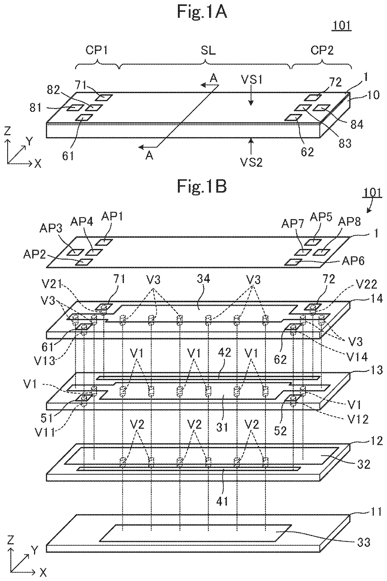
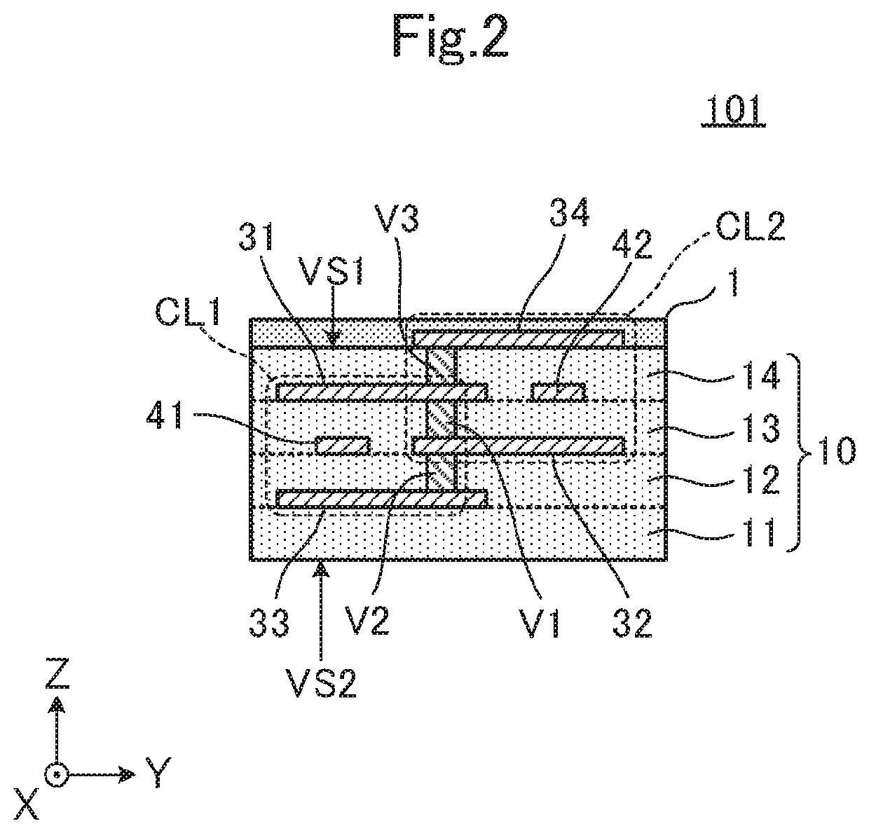
[0073]FIG. 1A is a perspective view of a multilayer substrate 101 according to a first preferred embodiment of the present invention, and FIG. 1B is an exploded perspective view of the multilayer substrate 101. FIG. 2 is an A-A cross-sectional view of the multilayer substrate 101 in FIG. 1A. The multilayer substrate is a non-limiting example of a “transmission line substrate” according to various preferred embodiments of the present invention.

[0074]The multilayer substrate 101 includes a stacked body 10 obtained by stacking a plurality of insulating base materials 11, 12, 13, and 14, a conductor (such as a first signal line 41, a second signal line 42, a first ground conductor 31, a second ground conductor 32, a third ground conductor 33, a fourth ground conductor 34, a first interlayer connection conductor V1, a second interlayer connection conductor V2, and a third interlayer connection conductor V3) provided in any one of the plurality of insulating base materials 11, 12, 13, and...

second preferred embodiment

[0109]A second preferred embodiment of the present invention describes a multilayer substrate including a stacked body 10A obtained by stacking two insulating base materials and a protective layer.

[0110]FIG. 5A is a perspective view of a multilayer substrate 102 according to the second preferred embodiment of the present invention and FIG. 5B is an exploded perspective view of the multilayer substrate 102. FIG. 6 is a B-B cross-sectional view of the multilayer substrate 102 in FIG. 5A.

[0111]The multilayer substrate 102 includes a stacked body 10A obtained by stacking a plurality of insulating base materials 12 and 13, a conductor provided on any one of the plurality of insulating base materials 12 and 13, and a protective layer 1. The stacked body 10A, as illustrated in FIG. 5B, is obtained by stacking the two insulating base materials 12 and 13 in this order. The stacked body 10A further includes the protective layer 1 provided on the first primary surface VS1 of the stacked body 1...

third preferred embodiment

[0119]A third preferred embodiment of the present invention describes a multilayer substrate further including a fifth ground conductor and a sixth ground conductor.

[0120]FIG. 7A is a perspective view of a multilayer substrate 103 according to the third preferred embodiment of the present invention and FIG. 7B is an exploded perspective view of a line portion SL of the multilayer substrate 103. FIG. 8 is a C-C cross-sectional view of the multilayer substrate 103 in FIG. 7A.

[0121]The multilayer substrate 103 is different from the multilayer substrate 101 according to the first preferred embodiment in that the multilayer substrate 103 further includes a conductor (a fifth ground conductor 35, a sixth ground conductor 36, a fourth interlayer connection conductor V4, a fifth interlayer connection conductor V5, a sixth interlayer connection conductor V6, and a seventh interlayer connection conductor V7) provided in any one of the plurality of insulating base materials 11, 12, 13, and 14....


PUM

PropertyMeasurementUnit
insulatingaaaaaaaaaa
flexibilityaaaaaaaaaa
thicknessaaaaaaaaaa

Abstract

A transmission line substrate includes a stacked body that includes insulating base materials, first and second signal lines, and first and second ground conductors. The second signal line is provided on a layer different from the layer of the first signal line and extends in parallel with the first signal line. The first ground conductor is provided on the same layer as the layer of the second signal line and overlapped with the first signal line when viewed in the Z-axis direction. The second ground conductor is provided on the same layer as the layer of the first signal line and overlapped with the second signal line when viewed in the Z-axis direction. A first transmission line includes the first signal line, the first ground conductor, and an insulating base material, and a second transmission line includes the second signal line, the second ground conductor, and the insulating base material.

Description

CROSS REFERENCE TO RELATED APPLICATIONS[0001]This application claims the benefit of priority to Japanese Patent Application No. 2016-098850 filed on May 17, 2016, Japanese Patent Application No. 2016-160664 filed on Aug. 18, 2016, Japanese Patent Application No. 2017-000843 filed on Jan. 6, 2017 and is a Continuation Application of PCT Application No. PCT / JP2017 / 018271 filed on May 16, 2017. The entire contents of each application are hereby incorporated herein by reference.BACKGROUND OF THE INVENTION1. Field of the Invention[0002]The present invention relates to a transmission line substrate, and more particularly to a transmission line substrate including a plurality of transmission lines and an electronic device including such a transmission line substrate.2. Description of the Related Art[0003]Conventionally, a transmission line substrate in which a stacked body obtained by stacking a plurality of insulating base materials includes a plurality of transmission lines has been know...

Claims


Application Information

Patent Timeline
Patent Type & Authority Patents(United States)
IPC IPC(8): H01B11/00H05K1/02H01P3/08H05K1/11H01B7/18H05K3/46
CPCH01B11/002H01B7/18H01P3/08H05K1/0221H05K1/11H05K1/0298H05K3/4697H05K2201/0723H05K2201/09018H05K2201/09236H05K2201/09618H05K2201/09709H05K3/0014H05K2203/1105H01P3/088H01P5/028
Inventor BABA, TAKAHIROZHAO, LIJUNXU, CHUKOYAMA, HIROMASAMATSUURA, SATOSHI
Owner MURATA MFG CO LTD
Why Eureka
Try Eureka