
Facial interface

a facial interface and facial technology, applied in the field of facial interfaces, can solve the problems of patient discomfort facial sores and unsightly pressure marks,

Active Publication Date: 2021-07-06
9428 2290 QUEBEC INC
View PDF16 Cites 0 Cited by
  • Summary
  • Abstract
  • Description
  • Claims
  • Application Information

AI Technical Summary

Benefits of technology

[0011]It is therefore a primary object, feature, and / or advantage of the present invention to overcome deficiencies in the art.
[0012]According to an embodiment, there is provided a facial interface comprising:
[0013]a flexible face contact layer configured to cover a user's face; and
[0014]a nasal layer configured to sealably cover an external nose region of the user,wherein the flexible face contact layer and the nasal layer provide fluid circulation of air through the user's nostrils.
[0015]The flexible face contact layer may be further configured to cover a neck region, a forehead, a temporal region, a cheek region, a jaw region, a chin region, of a user's face, or combinations thereof.
[0016]The flexible face contact layer may be further configured to cover the external nose region.

Problems solved by technology

Indeed, CPAP masks often results in patient discomfort caused by a persistent sensation of leaks of air on the face of the patient, irritations, rashes, and facial sores and other marks caused by prolonged wear of the mask.
However, air leakage being extremely unpleasant for the patients and causes dryness of the eye, causing the patients to tighten the mask, to obtain a better seal.
A problem thus arises when the mask is compressed against the patient's face in order for the mask to maintain a seal without any undue gas leaks around the periphery of the mask.
This can cause facial sores and unsightly pressure marks upon arising after sleeping with the mask.
These masks may cause facial sores and unsightly pressure marks.

Method used


Image

  • Facial interface
  • Facial interface
  • Facial interface

Examples


Embodiment Construction

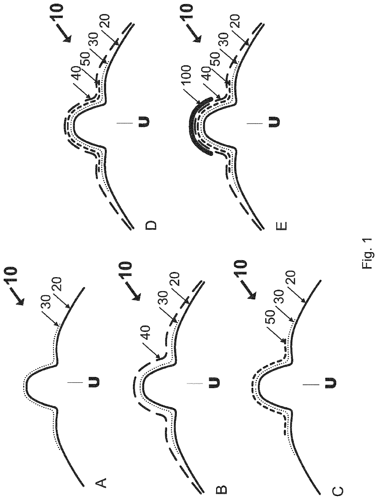
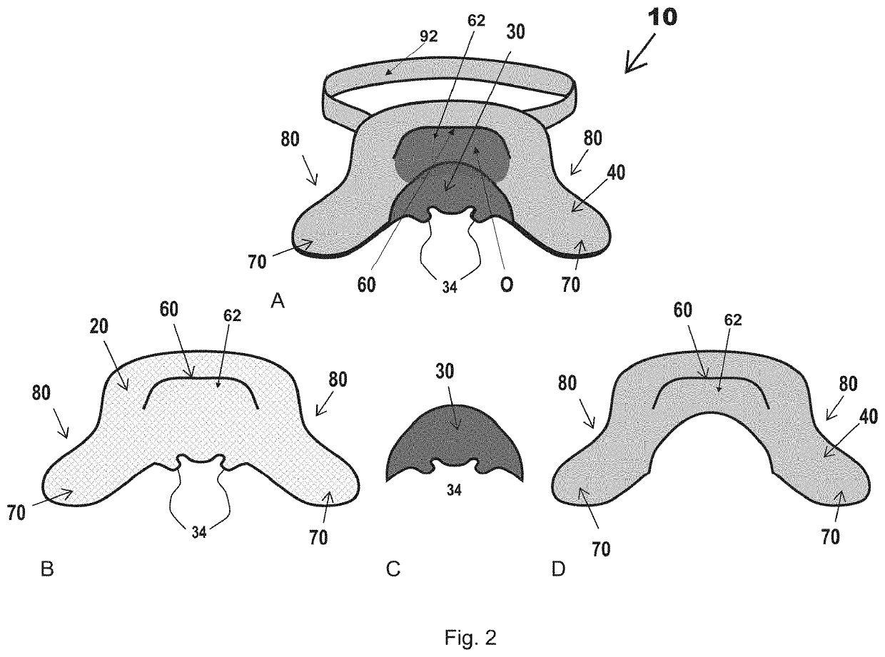
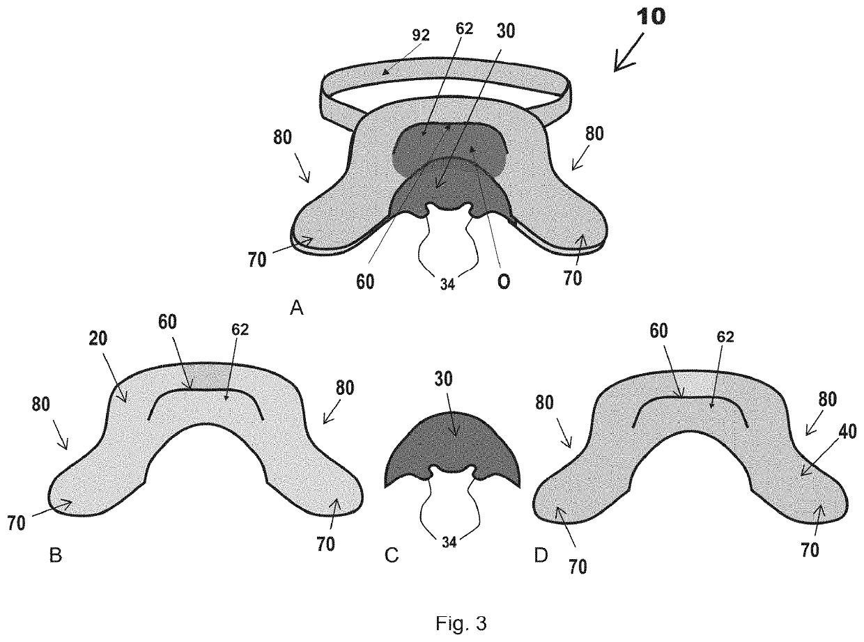
[0075]Referring now to the drawings, and more particularly to FIGS. 1 to 5 and 7, in embodiments there is disclosed a facial interface 10 comprising a flexible face contact layer 20, which is configured to cover a user's face. The facial interface 10 also comprises a nasal layer 30, which is configured to sealably cover an external nose region of the user. Each of the flexible face contact layer 20 and the nasal layer 30 provide fluid circulation of air through the user's nostrils. Now referring to FIGS. 7A-D, which illustrate embodiment where the flexible face contact layer 20 covers (A) the forehead, temporal region, cheek region, neck region, jaw chin regions, the nose and the eyes; (B) the forehead, temporal region, cheek region, neck region, the nose and the eyes; (C) temporal region, upper cheek region, the nose and the eyes; and (D) cheek region and the nose only. Preferably, the facial interface 10 is for use with a positive airway pressure device, but may be used in any oth...


PUM


Abstract

The present document describes a facial interface comprising a flexible face contact layer configured to cover a user's face; and a nasal layer configured to sealably cover an external nose region of said user. The flexible face contact layer and nasal layer provide fluid circulation of air through said user's nostrils.

Description

CROSS-REFERENCE TO RELATED APPLICATIONS[0001]This application is a US National Phase application under 35 USC § 371 of PCT / CA2017 / 050007, filed Jan. 5, 2017, which claims priority from and the benefit of U.S. Provisional Patent Application No. 62 / 275,526, filed Jan. 6, 2016, the specifications of which are hereby incorporated by reference in their entireties.BACKGROUND(a) Field[0002]The subject matter disclosed generally relates to facial interfaces. More particularly, the subject matter relates to a facial interface comprising a flexible face contact layer configured to cover a user's face; and a nasal layer, configured to sealably cover an external nose region of the user. The flexible face contact layer and the nasal layer provide fluid circulation of air through said user's nostrils.(b) Related Prior Art[0003]Continuous positive airway pressure (CPAP) is the use of positive pressure to maintain a continuous level of positive airway pressure to prevent collapse of airways in user...

Claims


Application Information

Patent Timeline
Patent Type & Authority Patents(United States)
IPC IPC(8): A61M16/06A61F5/08
CPCA61M16/0605A61F5/08A61M16/06A61M16/0616A61M16/0633A61M2205/02A61M2205/0238
Inventor BERNARD, LOUISE
Owner 9428 2290 QUEBEC INC
Learn More