Cylindrical filter cartridge device

Active Publication Date: 2021-07-06
BOESEL BRADLEY W
View PDF15 Cites 0 Cited by
  • Summary
  • Abstract
  • Description
  • Claims
  • Application Information

AI Technical Summary

Benefits of technology

[0004]The prior art devices have limitations. For example, such devices typically require considerable attention and/or effort by the person doing the cleaning. The present invention mini

Problems solved by technology

In the course of operating these filtration systems, the outer surface of a cartridge becomes contaminated and the cartridge must be replaced or cleaned.
Cleaning these cartridges is a more cost effective and environmentally friendly solution than replacement; however, cleaning this type of cartridge i

Method used


Image

  • Cylindrical filter cartridge device
  • Cylindrical filter cartridge device
  • Cylindrical filter cartridge device

Examples


Embodiment Construction

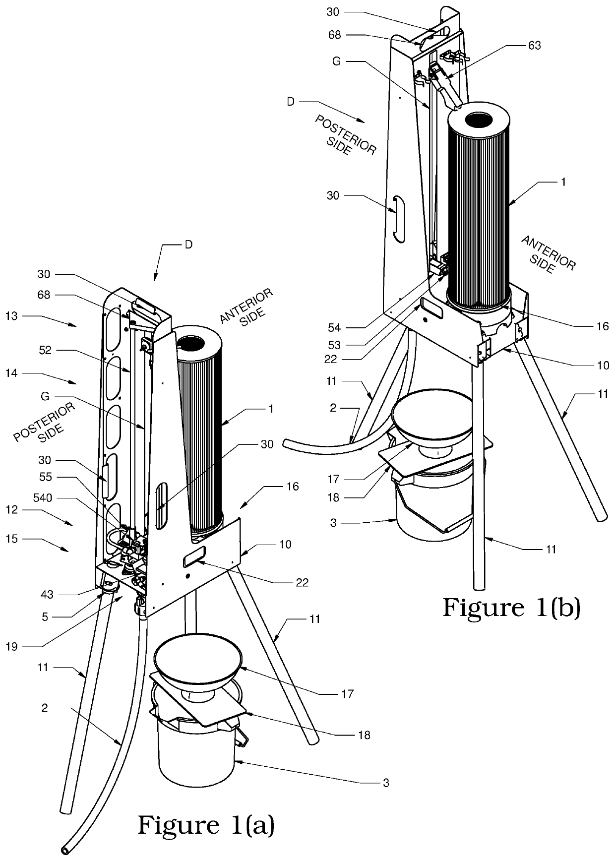
[0044]Herein, the terms “filter”, “filter cartridge”, and “cartridge”, element 1, are used interchangeably to refer to cylindrical filter elements having a longitudinal axis, an outer surface, an annular opening along the longitudinal axis, and ends substantially perpendicular to the longitudinal axis as shown in FIGS. 1(a), 1(b), 10(a), and 10(b). The outer surface of cartridge 1 may or may not be pleated and may or may not have a circular cross section. Examples of these type of cartridges 1 may be found in swimming pool, spa, and various industrial and commercial filtration systems.

[0045]Moreover, herein the term “working surface” is used to describe the surface of the cartridge 1 through which the fluid being filtered passes and upon which is deposited material removed from the fluid being filtered. This surface may also be described as the outer surface of a cartridge 1 as mentioned above.

[0046]Further, herein the term “pressurized water source” includes but is not limited to a...


PUM

PropertyMeasurementUnit
Torqueaaaaaaaaaa

Abstract

A cartridge cleaning device comprising a cleaning nozzle joined to means for vertically displacing the nozzle, a power unit, and a rotatable platform. Fluid is introduced to the device and split into two streams, one stream providing fluid to the cleaning nozzle and the other stream directed to the power unit and effectuating rotation of a power wheel, thereby generating a torque which is transferred to the means for vertically displacing the nozzle and the rotatable platform. The torque to the means for vertically displacing the cleaning nozzle effectuates vertical displacement of the nozzle. The torque to the rotatable platform effectuates rotation of the rotatable platform on which at least one cartridge is placed during cleaning operations. The cleaning nozzle directs a stream onto the cartridge surface and perpendicular to the cartridge longitudinal axis and is displaced vertically in concert with cartridge rotation.

Description

CLAIM OF PRIORITY[0001]This application is a divisional application claiming priority to and the benefit of Utility patent application Ser. No. 17 / 091,621, (viz., the “Parent Patent Application”), which in turn claimed the benefit of and priority to Provisional Patent Application No. 62 / 974,087 filed Nov. 12, 2019 (viz., the “Provisional Patent Application”). The entirety of each of the Parent Patent Application and Provisional Patent Application are incorporated herein by this reference.FIELD OF THE INVENTION[0002]The invention is an apparatus for automated cleaning of filter cartridges (referred to herein as well as “cartridges”) having a generally cylindrical shape with a longitudinal axis and planar ends substantially perpendicular to the longitudinal axis. Examples of such cartridges may be found in swimming pool and spa filtration systems as well as various commercial and industrial systems.BACKGROUND OF THE INVENTION[0003]Swimming pools, spas, and various commercial and indus...

Claims


Application Information

Patent Timeline
IPC IPC(8): B01D41/04B08B3/02
CPCB01D41/04B08B3/024
Inventor BOESEL, BRADLEY W.
Owner BOESEL BRADLEY W
Why Eureka
Try Eureka