Method and a system for guiding a pilot of an approaching aircraft to a stop position at a stand

a technology for approaching aircraft and stand, which is applied in the direction of instruments, transportation and packaging, and reradiation, etc., can solve the problems of large turning radius, high degree of interruption during docking, and inability to handle larger aircra

Active Publication Date: 2021-07-06
SAFEGATE INT
View PDF17 Cites 2 Cited by
  • Summary
  • Abstract
  • Description
  • Claims
  • Application Information

AI Technical Summary

Benefits of technology

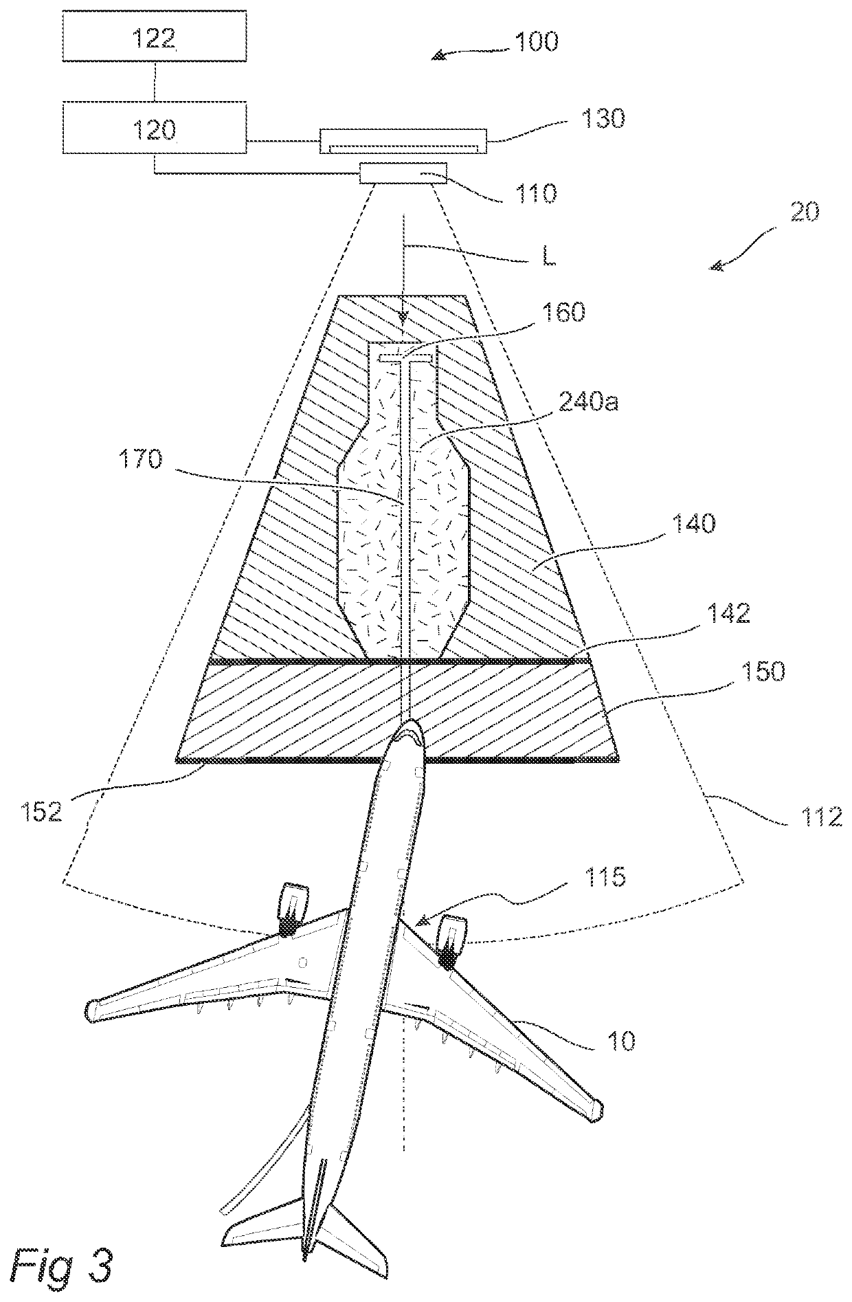
[0032]The method may be advantageous as it allows for providing a safer docking, especially for aircrafts of larger dimensions or automated safety from a wing clearance perspective at any stand designed for any aircraft dimensions, i.e. two adjacent narrow-bodied stands. According to the standards of ICAO and EASA, the wing tip clearance between neighboring aircrafts must be 7.5 meters unless the stand areas are monitored by aircraft docking systems to assist in the parking. Thus, as the disclosed method further increases the control of the approach and reduces the risk of collisions, the disclosed method may allow for new, larger, types of aircrafts to be parked at stands originally not designed and constructed to house such aircraft types. Furthermore, the method may be advantageous in situations where an aircraft for some reason has entered a stand area along a wrong lead-in line. The pilot may attempt to adjust the course of the aircraft to compensate, but in some cases the attempt may be unsuccessful, as the dimensions of the aircraft is too large for successful repositioning within the area available.
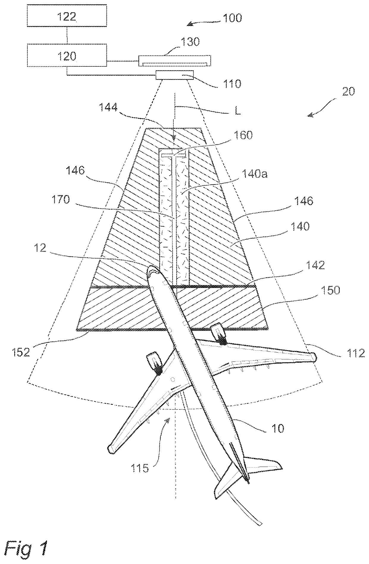
[0033]This is a result from a lowering of the risk of the aircraft coming too close to, or even crashing into, neighboring objects on its way to the stand. Moreover, the method may allow for a more flexible docking methodology at the airport. The flexibility has much to do with the ease by which the first area and the subsection thereof may be redefined dependent on the situation. Even if the infrastructure at an airport stand to some degree is fixed, and may be considered predefined, some parts of the infrastructure are not, such as e.g. a movable airport boarding bridge. By adjusting the first area and / or the subsection thereof, structural changes at the stand area may be accounted for. Furthermore, at stands designed with multiple lead-in lines for aircrafts approaching from different directions and / or for different types of aircraft, the system may adjust the first area and the subsection thereof dependent on which of the lead-in lines the approaching aircraft is assigned to follow. Should the pilot mistakenly drive the aircraft following the wrong lead-in line, the aircraft may enter the first area outside of the subsection of the first area, whereby the pilot would be instructed to stop the aircraft.
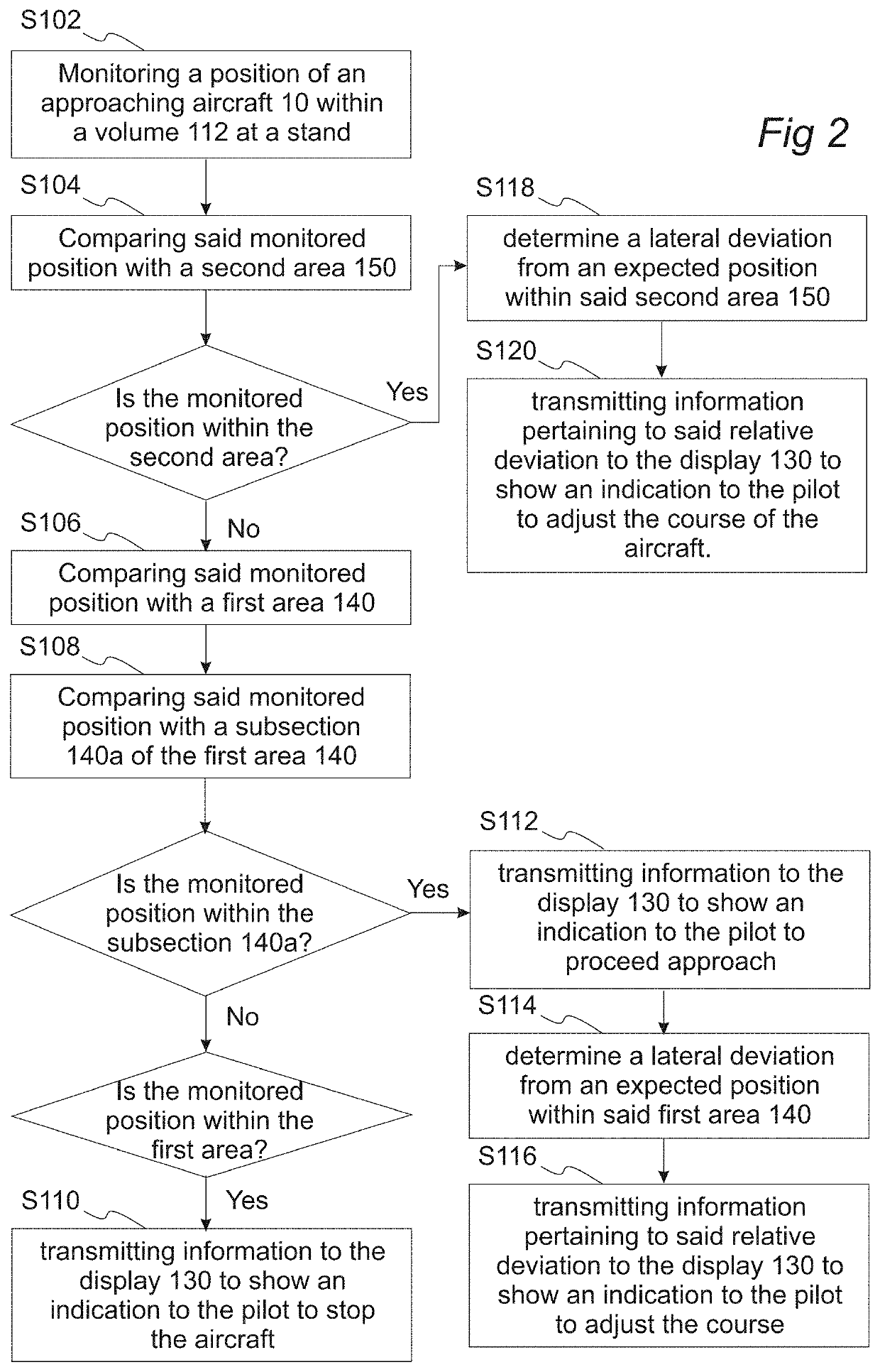
[0046]This may be advantageous as it allows for further optimizing the approach to the stop position of the stand. Thus, even in a case where the approaching aircraft is allowed to approach the stand, as determined by the monitored position being within the subsection of the first area, the aircraft is not necessarily aligned along the lead-in line in an optimal way. By allowing the system to continue guiding the pilot towards the stopping position, the parking may be improved. Furthermore, the risk is lowered that the aircraft moves such that the monitored position of the aircraft moves from the subsection of the first area to a subsection outside of the first area, at which the aircraft docking system would instruct the pilot to stop.
[0048]By adding the second area outside of the first area and allowing the docking system to, in the second area, actively guide the pilot towards a specific entrance position to the first area, the method will further improve the approach of the aircraft. The aircraft may thus be better prepared for entering the first area. While the monitored position is within the second area, there is no attempt to stop the aircraft. Instead, the pilot is given a chance to correct the approach path so that the monitored position of the approaching aircraft enters the subsection of the first area.
[0050]It is also conceivable that the line of positions inferred from the continuous monitoring of the position of the approaching aircraft is used to calculate the forward speed of the aircraft. The speed may then be used in different ways. For example, the first area and / or the subsection thereof may be adjusted as a function of the calculated speed. It may be an advantage to decrease the size of the subsection of the first area as a function of increasing speed, so as to lower the risk of collisions.
[0061]The term “lead-in line” should be interpreted as a guide path for the pilot for a specific approach. Typically, lead-in lines are marked on the ground by a painted line. A stand may, however, have more than one lead-in line. For example, a stand may have different lead-in lines for planes arriving from different directions, so as to decrease the angle the plane has to turn at, or close to, the stand area.

Problems solved by technology

In the latter case, the problem may instead be related to achieving a safe docking of the aircrafts.
Larger aircrafts have larger distance between their wheels, thus resulting in a larger turning radius.
A problem with known methods and systems is that they are not adapted to handle the larger aircrafts of increasing importance today.
Even if the physical dimensions of the aircrafts would fit the stand, the aircraft docking systems, and the methods implemented therein are not adapted to handle the docking in a correct way which may lead to high degree of interruptions during docking, or even accidents.
The pilot may attempt to adjust the course of the aircraft to compensate, but in some cases the attempt may be unsuccessful, as the dimensions of the aircraft is too large for successful repositioning within the area available.
This is a result from a lowering of the risk of the aircraft coming too close to, or even crashing into, neighboring objects on its way to the stand.
Thus, even in a case where the approaching aircraft is allowed to approach the stand, as determined by the monitored position being within the subsection of the first area, the aircraft is not necessarily aligned along the lead-in line in an optimal way.
However, this is not always the case.

Method used


Image

  • Method and a system for guiding a pilot of an approaching aircraft to a stop position at a stand
  • Method and a system for guiding a pilot of an approaching aircraft to a stop position at a stand
  • Method and a system for guiding a pilot of an approaching aircraft to a stop position at a stand

Examples


Embodiment Construction

[0069]The present invention will now be described more fully hereinafter with reference to the accompanying drawings, in which currently preferred embodiments of the invention are shown. This invention may, however, be embodied in many different forms and should not be construed as limited to the embodiments set forth herein; rather, these embodiments are provided for thoroughness and completeness, and fully convey the scope of the invention to the skilled person.

[0070]FIG. 1 shows an aircraft docking system 100 according to an example embodiment. The aircraft docking system 100 comprises a position monitoring system 110 being arranged to monitor a position of the approaching aircraft 10 within a volume 112 at the stand 20. The position monitoring system 110 is a laser-based position monitoring system adapted to continuously scan the volume 112 at the stand 20. A laser beam is emitted from the position monitoring system 110 e.g. via a vibrating mirror arrangement or an acousto-optic...


PUM


Abstract

The disclosure relates to a method for guiding a pilot of an approaching aircraft to a stop position at a stand, said method being characterized by: monitoring a position of the approaching aircraft within a volume at the stand, comparing said monitored position with a first area, said first area enclosing the stop position, comparing said monitored position with a subsection of the first area enclosing the stop position, if said monitored position is inside said subsection: transmitting information to a display to show an indication to the pilot to proceed approaching the stand, and if said monitored position is inside the first area but not inside said subsection: transmitting information to the display to show an indication to the pilot to stop the aircraft. The disclosure further relates to an aircraft docking system.

Description

CROSS-REFERENCE TO RELATED APPLICATIONS[0001]The present application is a bypass continuation of and claims priority to PCT / EP2019 / 065796, filed Jun. 17, 2019, which claims priority to European Patent Application No. 18178233.5, filed Jun. 18, 2018. The contents of these applications are incorporated herein by reference in their entirety.FIELD OF THE INVENTION[0002]The present invention relates to a method for guiding a pilot of an approaching aircraft to a stop position at a stand. The invention further relates to an aircraft docking system.BACKGROUND ART[0003]The greater demands on increased fuel economy have forced aircraft manufacturers to produce larger aircrafts to decrease fuel consumption per passenger seat. As airlines make corresponding changes to their fleets exchanging smaller aircrafts with larger ones, airports have been forced to develop means for efficiently and safely handling these larger aircrafts. As an example, many international airports have been forced to inc...

Claims


Application Information

Patent Timeline
Patent Type & Authority Patents(United States)
IPC IPC(8): G08B5/00B64F1/00G08G5/00G08G5/06G01S13/934
CPCB64F1/002G08G5/0026G08G5/065G01S17/42G01S17/88G08G5/0082G01S13/934Y02T50/80B64F1/00G01S17/93G08G5/00
Inventor BERKMO, ANDERS
Owner SAFEGATE INT
Why Eureka
Try Eureka