Key structure

Active Publication Date: 2021-07-06
ACER INC
View PDF10 Cites 1 Cited by
  • Summary
  • Abstract
  • Description
  • Claims
  • Application Information

AI Technical Summary

Benefits of technology

The invention provides a key structure that is stronger and more durable. The design integrates a sound structure into the key cap and its spring, making it easier to press and providing a better auditory experience for the user. This allows for smaller key structures while maintaining their strength and functionality.

Problems solved by technology

However, the aforementioned sound structure design has poor structural integrity, and it is difficult to meet design requirements of product miniaturization.

Method used


Image

  • Key structure
  • Key structure
  • Key structure

Examples


Embodiment Construction

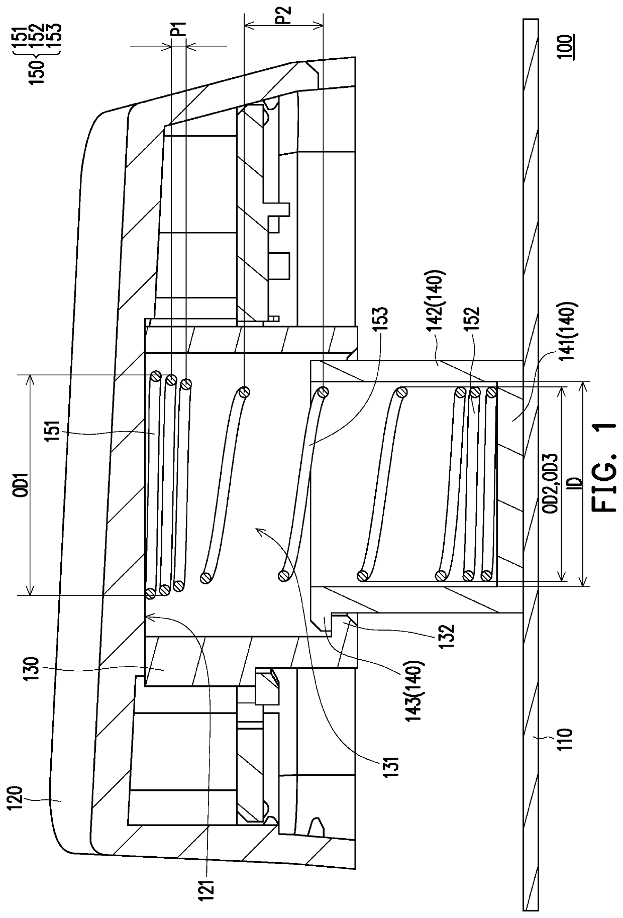
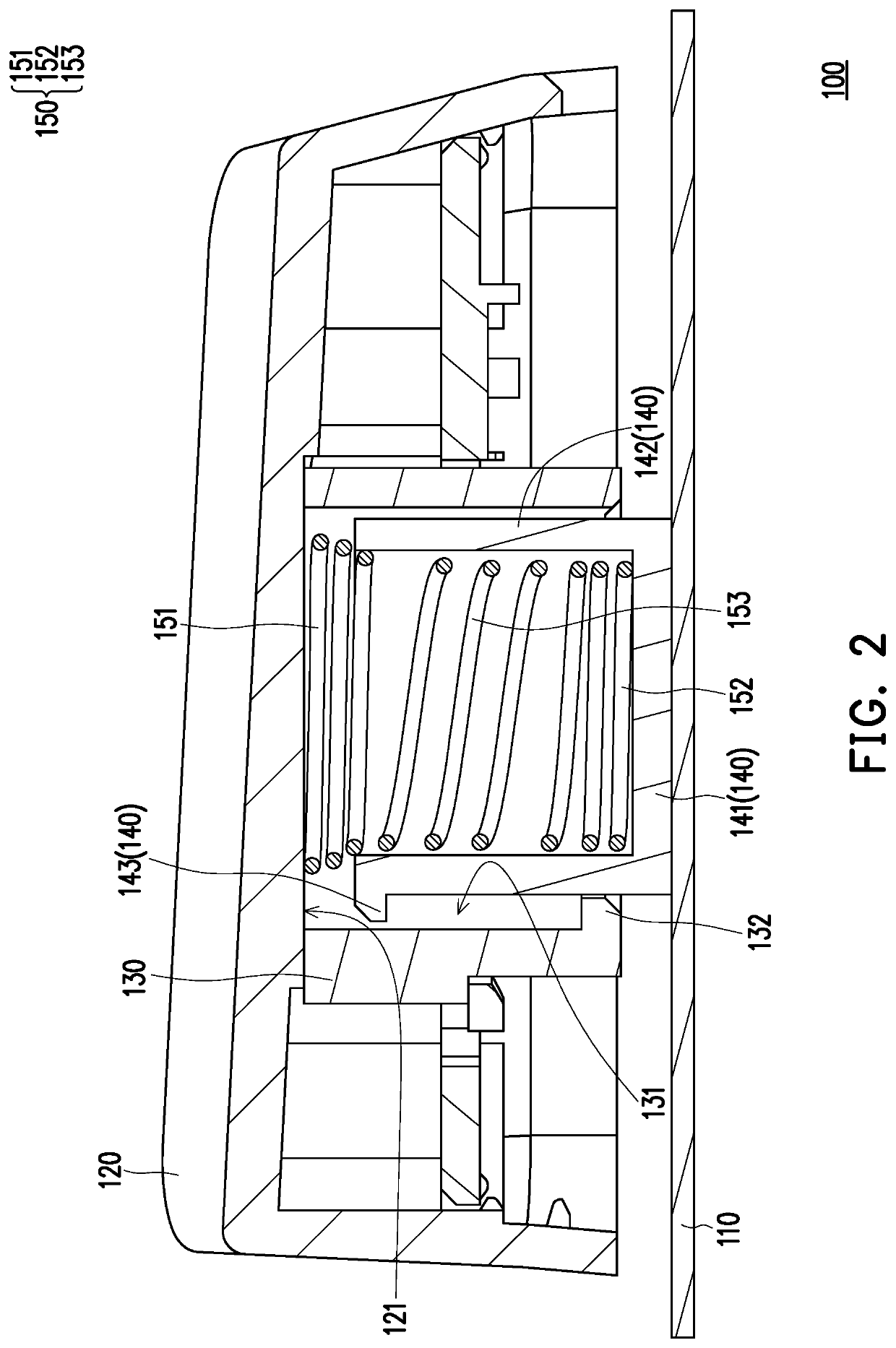
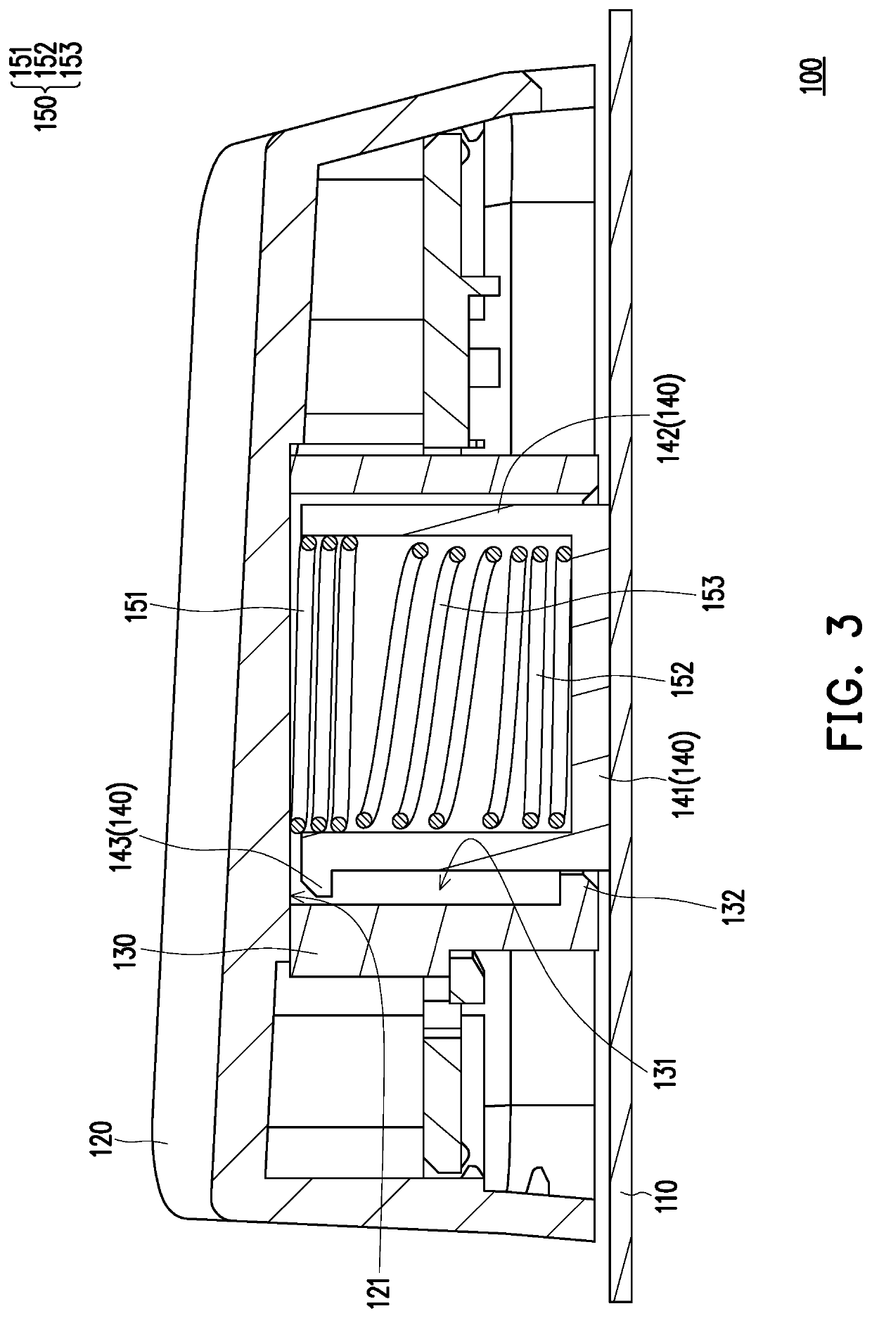
[0012]FIG. 1 is a schematic cross-sectional view of a key structure according to an embodiment of the invention. FIG. 2 is a schematic cross-sectional view of switching the key structure in FIG. 1 to another state. FIG. 3 is a schematic cross-sectional view of switching the key structure in FIG. 2 to a next state. Referring to FIG. 1, in the present embodiment, a key structure 100 may be applied to a keyboard and used as a physical operation interface for a user to input a signal to a desktop computer, a notebook computer, or other electronic apparatuses. In particular, the key structure 100 includes a base plate 110, a key cap 120, a positioning base 130, a positioning cover 140, and a spring 150. The key cap 120 is disposed above the base plate 110, and the spring 150 is configured to support the key cap 120. The spring 150 is located between the key cap 120 and the base plate 110, and is covered by the positioning base 130 and the positioning cover 140. In other words, the positi...


PUM


Abstract

A key structure includes a base plate, a key cap, a positioning base, a positioning cover, and a spring. The key cap is disposed above the base plate and has a bottom surface. The positioning base is connected to the bottom surface of the key cap and has a positioning recess. The positioning cover is slidably connected to the positioning base, is inserted into the positioning recess, and includes a bottom portion and a side wall. The spring includes a first spring portion and a second spring portion. The first spring portion is located in the positioning recess and is in contact with the bottom surface of the key cap. The second spring portion is located in the positioning cover. The first spring portion is located on a path on which the side wall of the positioning cover slides toward the bottom surface of the key cap.

Description

CROSS-REFERENCE TO RELATED APPLICATION[0001]This application claims the priority benefit of Taiwan application serial no. 109101704, filed on Jan. 17, 2020. The entirety of the above-mentioned patent application is hereby incorporated by reference herein and made a part of this specification.BACKGROUNDTechnical Field[0002]The disclosure relates to a key structure, and in particular, to a key structure applied to a keyboard.Description of Related Art[0003]As a common physical input device, a keyboard is widely applied to the desktop computer, the notebook computer, or other electronic apparatuses. Generally, the keyboard includes a plurality of key structures, and a shaft body adopted in the key structure may include a mechanical shaft, a rubber dome shaft, or a spring shaft.[0004]Taking the key structure using the spring shaft (for example, a compression spring) as an example, the design of such a key structure is mostly integrated with an elastic piece. Therefore, in the process of...

Claims


Application Information

Patent Timeline
IPC IPC(8): H01H13/7073
CPCH01H13/7073H01H13/84H01H2215/03H01H2235/01H01H2235/018H01H2235/03
Inventor CHEN, HUNG-CHILIN, CHENG-HAN
Owner ACER INC
Why Eureka
Try Eureka