System for the treatment of water

a technology for treating systems and water, applied in the direction of battery/cell propulsion, vehicle cleaning, electrochemical generators, etc., can solve the problems of increased installation space, increased cost, and increased weight, and achieve the effect of reducing the emission of water or water vapor from the system, saving costs and weight, and positive effect on its operation

Active Publication Date: 2021-07-06
AUDI AG
View PDF10 Cites 0 Cited by
  • Summary
  • Abstract
  • Description
  • Claims
  • Application Information

AI Technical Summary

Benefits of technology

[0026]It is possible here for the system to have the additional system outer wall, wherein this additional system outer wall and the condenser enclose the air duct, through which the airflow flows when the vehicle is in motion. A speed-dependent negative pressure is thereby created within the air duct, evaporated by the water, and a cooling effect for cooling the condenser is produced. It is thereby possible to control the airflow automatically or manually by means of flaps inside the air duct.
[0028]The exhaust system presented integrates a plurality of functions, namely a directing of exhaust gas comprising water vapor out of the at least one fuel cell, as well as a cooling of this exhaust gas, wherein otherwise customary components are dispensed with and an available cavity is optimally used for transporting the water. Furthermore, costs and weight are to be saved. By dint of early condensing out, the exhaust system can be shortened and end before a rear axle of the vehicle. Moreover, due to evaporation of the water resulting from an effect of the airflow, an additional cooling potential is to be realized which, with respect to a high cooling requirement of the at least one fuel cell, has a positive impact on its operation. Moreover, an emission of water or water vapor from the system is significantly reduced. If water from the at least one fuel cell is completely reused or recycled, it is possible that a vehicle having this system is also to be operated free of emissions which contain water. With the system presented, water vapor is effectively cooled. The system presented, by reason of its effective mode of operation, only requires minimal installation space so that, starting in a front-end region, it only extends as far as the middle of the vehicle.
[0029]With one possible realization of the system, it is provided that a covering of the underbody has a sandwich structure comprising, for example, the closed cavity and the condenser which are arranged one on top of the other. A connection of the system to a system comprising at least one fuel cell is, for example, realized via an interface in the front-end area of the cavity. In one embodiment, the at least one fuel cell of the vehicle is arranged in a vertical direction or z direction of the vehicle above the cavity and / or an inlet of the cavity. The interface is arranged in a vertical direction between the at least one fuel cell and the cavity. It is thus possible for water vapor from the at least one fuel cell to be conveyed into the cavity by the effect of gravity. It is possible here to connect the interface to the at least one fuel cell. This is to be ensured, for example, by a simple mounting.

Problems solved by technology

However, for this purpose a plurality of individual components, an increase in the installation space required, increased costs, and an increased weight are to be expected.
Accordingly, the exhaust system has a complex design which is due inter alia to the requirement that the exhaust system is to be taken as far as the rear of the vehicle.

Method used


Image

  • System for the treatment of water
  • System for the treatment of water
  • System for the treatment of water

Examples


first embodiment

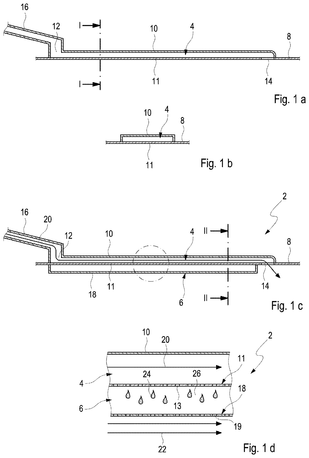
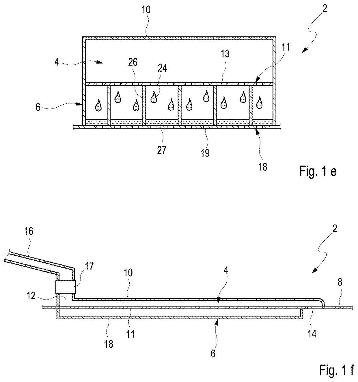
[0036]the system 2 according to the disclosure is shown in full in FIG. 1c. FIG. 1d shows a first detail of the system 2 marked in FIG. 1c by a dashed circle. FIG. 1e shows a second detail from FIG. 1c along a section line II-II. This system 2 comprises a cavity 4 and a condenser 6. The cavity 4 is shown without the condenser 6 in FIG. 1a. FIG. 1b shows the cavity 4 in sectional view along a line I-I from FIG. 1a. As FIG. 1c shows, the condenser 6 is arranged between the vehicle outer wall 8 and a system outer wall 18, which simultaneously bounds the underbody of the vehicle. Figure if shows the complete system 2 from a second perspective.

[0037]Here, it is provided that the cavity 4 is arranged on an underbody-side vehicle outer wall 8 of the vehicle and is bounded by a first cavity outer wall 10 and a second cavity outer wall 11, which is designed as part of the underbody-side vehicle outer wall 8. The second cavity outer wall 11 has pores 13 which are discernible in FIG. 1e.

[0038...

second embodiment

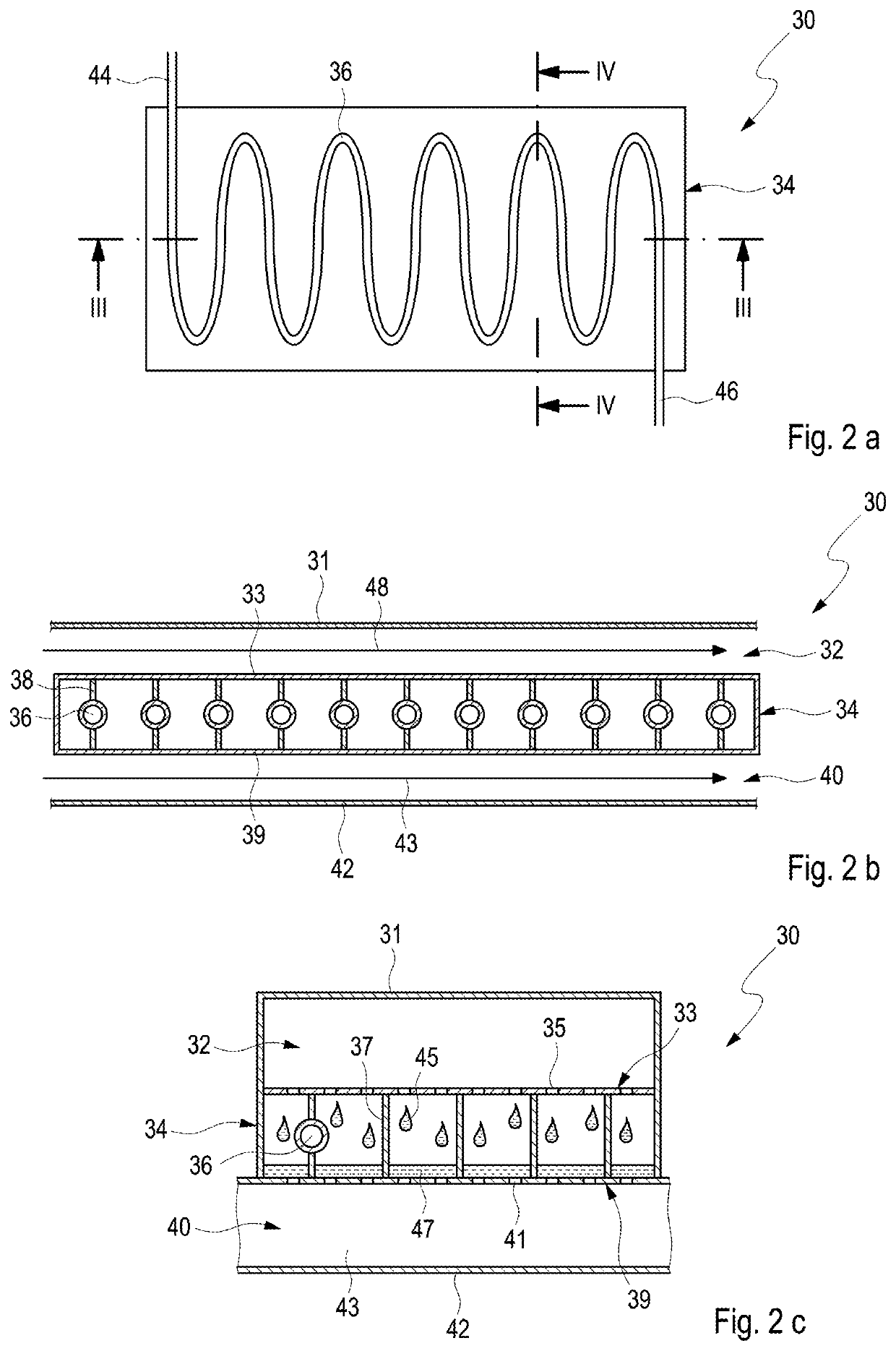
[0042]FIG. 2a shows a condenser 34 of the system 30 from above, wherein it can be seen here that a cooling duct 36 is connected via two connections 44, 46 to a loop of a thermal management system. FIG. 2b shows a detail of the system 30 along a section line from FIG. 2a. FIG. 2c shows the system 30 along a section line IV-IV from FIG. 2a.

[0043]The second embodiment of the system 30 for a vehicle is shown schematically in FIG. 2b. This system 30 also comprises a cavity 32, the condenser 34 with cooling ducts 36 and cooling ribs 38 and an air duct 40, wherein the condenser 34 is arranged between the cavity 32 and the air duct 40, wherein the system 30 is bounded here by an underbody-side system outer wall 42, which simultaneously forms an underride protection plate of an underbody of the vehicle. The cavity 32 is bounded by a first cavity outer wall 31 and a second cavity outer wall 33, which is simultaneously formed as first condenser outer wall of the condenser 34 and has pores 35....


PUM

PropertyMeasurementUnit
temperatureaaaaaaaaaa
weightaaaaaaaaaa
pressureaaaaaaaaaa

Abstract

The disclosure relates to a system for the treatment of water formed during an operation of at least one fuel cell of a vehicle, having a cavity, a condenser and an underbody-side system outer wall, and is designed to bound an underbody of the vehicle, wherein the condenser is arranged between the cavity and the underbody-side system outer wall, wherein the cavity is connected via an inlet to the at least one fuel cell, wherein, when the vehicle is in motion, the condenser is acted upon by air of an airflow and is cooled, wherein the condenser is designed to cool water which, originating from the at least one fuel cell, flows into the cavity.

Description

BACKGROUNDTechnical Field[0001]The disclosure relates to a system and a method for the treatment of water from at least one fuel cell of a vehicle.Description of the Related Art[0002]A vehicle that is powered by fuel cells has an exhaust system provided for this purpose with which water vapor from the fuel cells, which is for example at a temperature of approx. 60° C. to 70° C., is conveyed from a front end to a rear end of a vehicle and discharged. An exhaust system of this type is for example made from plastic and installed in the vehicle as a separate individual assembly. Furthermore, it is provided that the exhaust system has a constant downward slope or a drop. Moreover, reservoirs for water may be installed in the exhaust system, in which reservoirs water from the fuel cells is collected and regularly drained off.[0003]However, for this purpose a plurality of individual components, an increase in the installation space required, increased costs, and an increased weight are to ...

Claims


Application Information

Patent Timeline
Patent Type & Authority Patents(United States)
IPC IPC(8): H01M8/04H01M8/04014B60S1/50H01M8/04119B60L50/72H01M8/04007
CPCH01M8/04164B60L50/72B60S1/50H01M8/04014H01M8/04059H01M8/04141H01M2250/20H01M8/04298H01M8/0662Y02T90/40Y02E60/50
Inventor MAIER, JOSEFLANDGRAF, JOHANNESLEMEZYS, BENJAMIN
Owner AUDI AG
Why Eureka
Try Eureka