Rotary extending frame

a technology of extending frame and rotating frame, which is applied in the direction of machine supports, instruments, furniture parts, etc., can solve the problems of reducing the repair or replacement effect, and achieve the effects of reducing the rotation speed, avoiding collision damage of the rotary extending frame and the chassis, and convenient repair or replacemen

Active Publication Date: 2021-07-06
COMPAL ELECTRONICS INC
View PDF13 Cites 2 Cited by
  • Summary
  • Abstract
  • Description
  • Claims
  • Application Information

AI Technical Summary

Benefits of technology

[0005]The invention provides a rotary extending frame, which is capable of providing a simple way to repair or replace electronic modules installed inside and capable of avoiding collision damage of the rotary extending frame.
[0007]Based on the above, the rotary extending frame of the invention is suitable for being disposed in the chassis of the server. Through the driving of the handle, the rotary extending frame may rotate relative to a chassis body, and the accommodation spaces of the frame can be lifted upwards without being blocked, so that the electronic modules installed in the accommodation spaces of the frame can be conveniently repaired or replaced by users. Furthermore, each handle of the invention is clamped by each friction piece and the frame. When the handle rotates relative to the frame, the rotating portions, the positioning discs and the friction pieces produce bidirectional contact friction, so that the rotation speed can be reduced when the frame rotationally drops down, and thus the collision damage of the rotary extending frame and the chassis can be avoided.

Problems solved by technology

When one of the extending areas needs to be repaired or replaced, all extending areas must be disassembled and separated one by one, which is not conducive to the repair or replacement.

Method used


Image

  • Rotary extending frame
  • Rotary extending frame
  • Rotary extending frame

Examples


Embodiment Construction

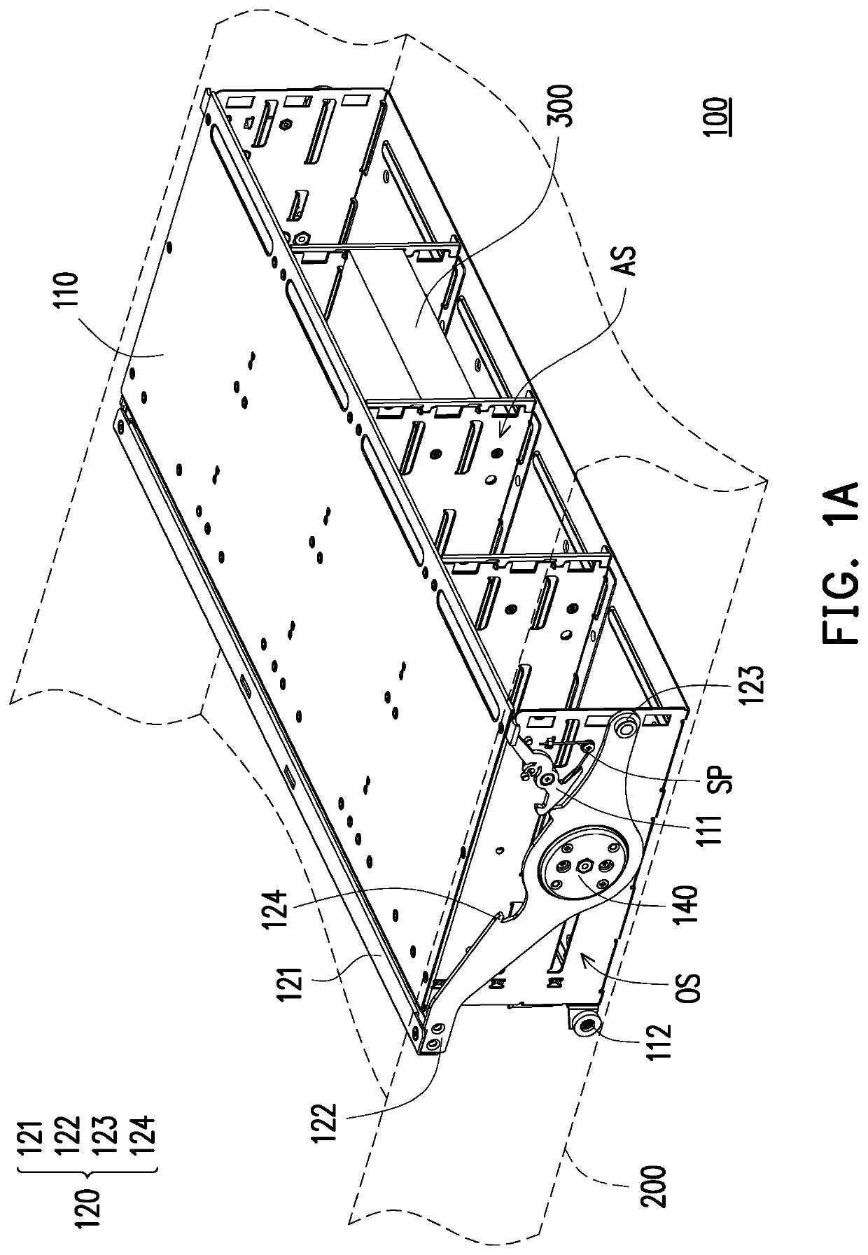
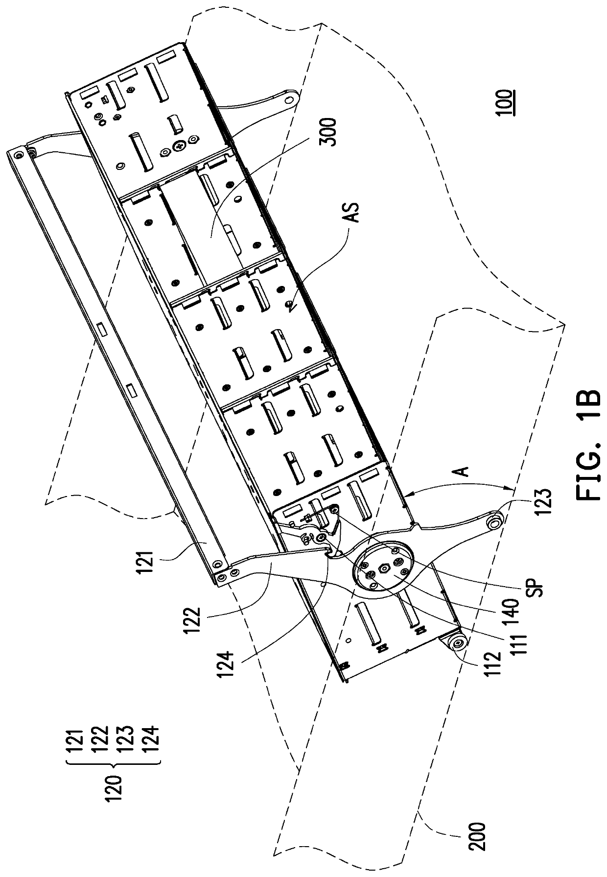
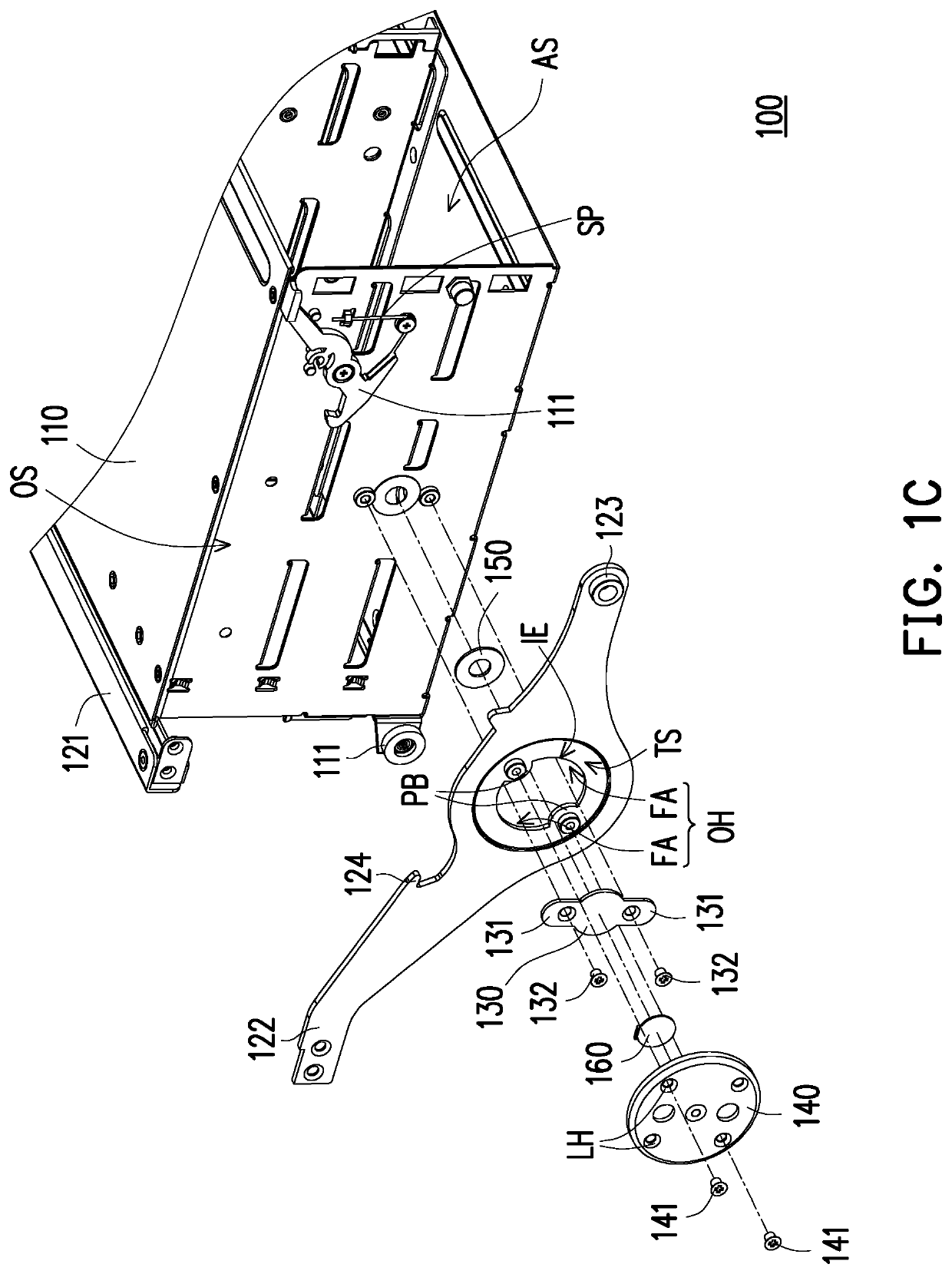
[0013]FIG. 1A is a schematic stereoscopic view of a rotary extending frame in a storage mode according to an embodiment of the invention. FIG. 1B is a schematic stereoscopic view of the rotary extending frame of FIG. 1A in a lifting mode. FIG. 1C is a schematic exploded stereoscopic view of components of the rotary extending frame of FIG. 1A.

[0014]Referring to FIG. 1A and FIG. 1B, the rotary extending frame 100 of the invention is suitable for being disposed in a chassis 200 of a server. As shown in FIG. 1A and FIG. 1B, only a single rotary extending frame 100 is disposed in the chassis 200, and only one electronic module 300 is shown in the rotary extending frame 100. In actual use, a plurality of rotary extending frames 100 may be installed in the chassis 200. A plurality of electronic modules 300 may be disposed in each rotary extending frame 100, which depends on the requirements of users or servers. In the invention, the electronic module 300, for example, is a hard disk module...


PUM


Abstract

A rotary extending frame includes a frame, a handle, a plurality of friction pieces, and a plurality of positioning discs. The frame has a plurality of accommodation spaces and fastening portions. The handle is rotatably disposed on the frame and has a holding portion and a plurality of rotating portions connected to two ends of the holding portion and facing two side surfaces of the frame respectively. The friction pieces are disposed on the corresponding rotating portions respectively and are firmly attached on the two side surfaces. The positioning discs are disposed on the corresponding rotating portions respectively and are pivotally connected to the friction pieces. The friction pieces and the frame clamp the corresponding rotating portions, so that the rotating portions and the positioning discs are adapted to rotate relative to the friction pieces and the frame and rub against the corresponding friction pieces simultaneously.

Description

CROSS-REFERENCE TO RELATED APPLICATION[0001]This application claims the priority benefit of Taiwan application serial no. 108134616, filed on Sep. 25, 2019. The entirety of the above-mentioned patent application is hereby incorporated by reference herein and made a part of this specification.BACKGROUND OF THE INVENTION1. Field of the Invention[0002]The invention relates to an extending frame, in particular, to a rotary extending frame for carrying hard disks.2. Description of Related Art[0003]A server is a core computer serving computers or portable electronic devices in a network system, is capable of providing functions required by network users such as hard disks or printing services, and is also available for clients to share various resources in the network environment. In order to store a great amount of data, the server needs to be configured with a plurality of hard disk modules.[0004]A large chassis is adopted in the prior art. A plurality of hard disk modules are respectiv...

Claims


Application Information

Patent Timeline
Patent Type & Authority Patents(United States)
IPC IPC(8): A47B96/00H05K7/14F16M13/02
CPCH05K7/1489F16M13/022F16M2200/024G06F1/187G11B33/0461F16M11/10F16M13/04G11B33/127
Inventor YU, WEI-CHENG
Owner COMPAL ELECTRONICS INC
Why Eureka
Try Eureka