Transport block transmission method and transmission device

a technology of transport block and transmission method, which is applied in the field of wireless communication system to achieve the effect of reducing delay/latency in the communication process between user equipment and base station, efficient transmission/receiving, and improving overall throughput of radio communication system

Active Publication Date: 2021-07-13
LG ELECTRONICS INC
View PDF3 Cites 1 Cited by
  • Summary
  • Abstract
  • Description
  • Claims
  • Application Information

AI Technical Summary

Benefits of technology

[0019]According to example(s) of the present invention, uplink / downlink signals can be efficiently transmitted / received. Therefore, overall throughput of a radio communication system can be improved.
[0020]According to an embodiment of the present invention, delay / latency occurring in a process of communication between a user equipment and a base station may be lowered.
[0021]With development of smart devices, small volumes of data may be efficiently transmitted / received or less frequently generated data may be efficiently transmitted / received.
[0022]According to example(s) of the present invention, delay / latency occurring during communication between a user equipment and a base station may be reduced.
[0023]It will be appreciated by persons skilled in the art that that the effects that can be achieved through the present invention are not limited to what has been particularly described hereinabove and other advantages of the present invention will be more clearly understood from the following detailed description.

Problems solved by technology

In addition, massive machine type communication (mMTC) for providing various services anytime and anywhere by connecting a plurality of devices and objects to each other is one main issue to be considered in future-generation communication.

Method used


Image

  • Transport block transmission method and transmission device
  • Transport block transmission method and transmission device
  • Transport block transmission method and transmission device

Examples


case b

[0088] Transmission in mmWave Band

[0089]Since an mmWave band (e.g., a band of 6 GHz or above) is sensitive to movement of a user, a variation width of a received SNR or signal-to-interference-plus-noise ratio (SINR) may be greater than an LTE / LTE-A band (e.g., a band of 2 GHz). Therefore, since performance reduction width caused by use of the syndrome check in the mmWave band may be relatively smaller than that in the LTE / LTE-A band, the syndrome check may be used in the mmWave band.

case c

[0090] Small TB Transmission

[0091]In LTE / LTE-A, the smallest TB is 40 bits. However, since a CRC uses 24 bits, overhead caused by the CRC is 24 / (40+24), which is about 1 / 3. Accordingly, the syndrome check may be used instead of the CRC with respect to a TB of a predetermined size or less in order to reduce overhead.

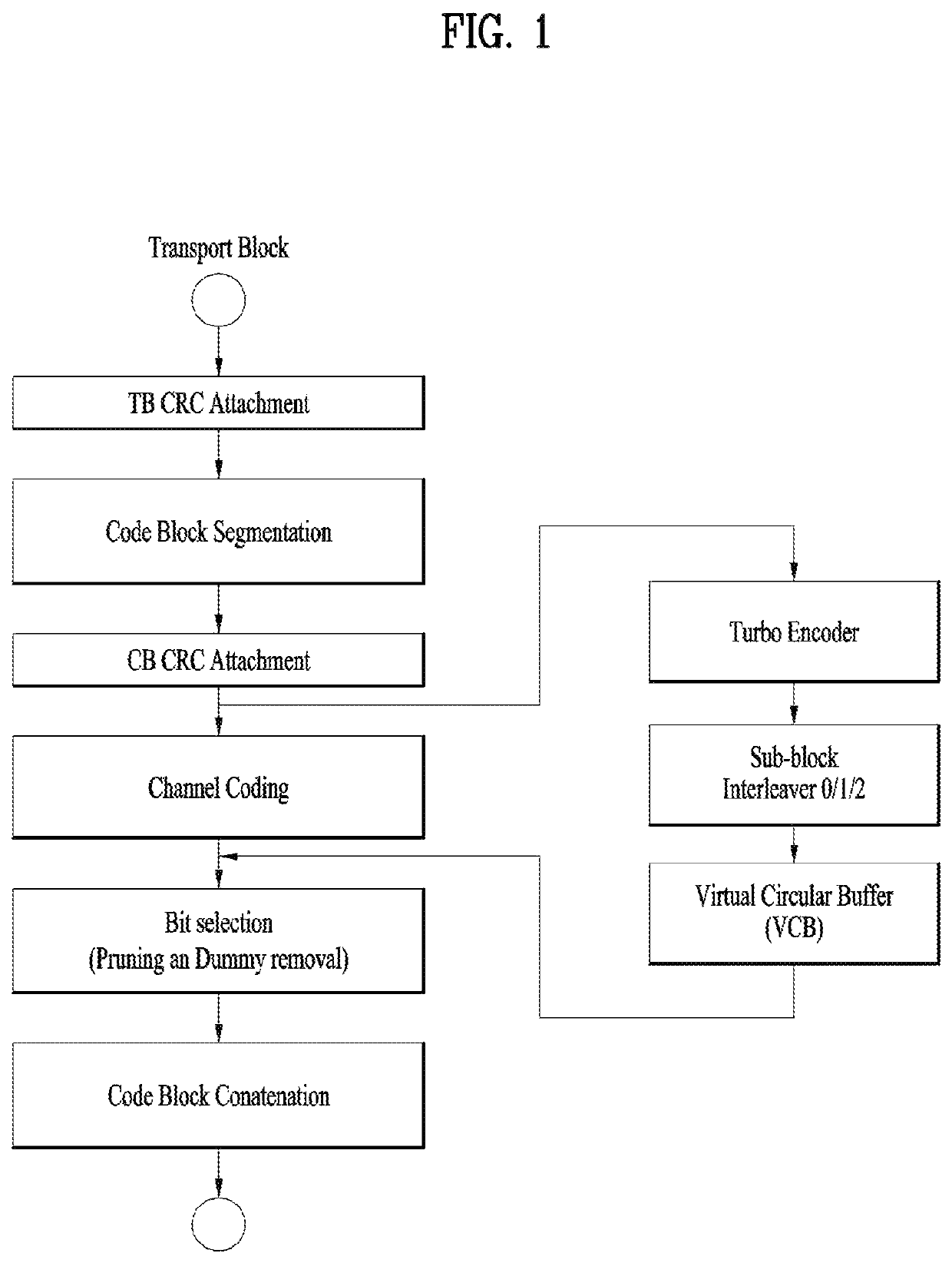
[0092]FIG. 8 illustrates a coding chain considering use of a CRC and a syndrome check according to the present invention.

[0093]The transmitting device attaches a TB CRC code to a TB to generate a TB CRC-attached TB (S801). The transmitting device segments the TB CRC-attached TB into a plurality of CBs (S802) (when the TB CRC-attached TB exceeds a specific maximum size capable of being encoded by the encoder) The transmitting device may determine whether to attach a CB CRC code to each of the plural CBs so that the decoder of the receiving device may perform a CRC upon a CB or to cause the decoder to perform the syndrome check upon the CB without adding the CB CRC (S803), ...


PUM


Abstract

A transmission device in a wireless communication system attaches a cyclic redundancy check (CRC) code having a predetermined length to a code block (CB) acquired from a transport block (TB). The predetermined length according to the present invention depends on a code rate associated with the TB.

Description

CROSS-REFERENCE TO RELATED APPLICATIONS[0001]This application is the National Stage filing under 35 U.S.C. 371 of International Application No. PCT / KR2018 / 001577, filed on Feb. 6, 2018, which claims the benefit of U.S. Provisional Application No. 62 / 455,581, filed on Feb. 6, 2017, the contents of which are all hereby incorporated by reference herein in their entireties.TECHNICAL FIELD[0002]The present invention relates to a wireless communication system and, more particularly, to a method and apparatus for transmitting a transport block.BACKGROUND ART[0003]With appearance and spread of machine-to-machine (M2M) communication, machine type communication (MTC) and a variety of devices such as smartphones and tablet Personal Computers (PCs) and technology demanding a large amount of data transmission, data throughput needed in a cellular network has rapidly increased. To satisfy such rapidly increasing data throughput, carrier aggregation technology, cognitive radio technology, etc. for...

Claims


Application Information

Patent Timeline
Patent Type & Authority Patents(United States)
IPC IPC(8): H04L1/00H04L1/06
CPCH04L1/0063H04L1/0003H04L1/0071H04L1/0643H04L1/0009H04L1/0015H04L1/0041H04L1/0045H04L1/0061H04L1/00
Inventor NOH, KWANGSEOKKIM, BONGHOE
Owner LG ELECTRONICS INC
Why Eureka
Try Eureka