Multiple angle offset optic mount

a technology of optic mounts and offsets, applied in the field of multi-angle offset optic mounts, can solve the problems of limited user's ability to select the desired eye relief, low or no flexibility in mounting positions, and offset optic mounts

Active Publication Date: 2021-07-20
ARISAKA LLC
View PDF6 Cites 13 Cited by
  • Summary
  • Abstract
  • Description
  • Claims
  • Application Information

AI Technical Summary

Problems solved by technology

However, prior art offset optic mounts have several disadvantages.
First, they offer little or no flexibility in regards to mounting position.
This limits the user's ability to select a desired eye relief for the offset electronic sight.
Second, they offer little or no flexibility in regards to the offset angle afforded the attached electronic sight.
This can inhibit use of the electronic sight with telescopic sights that are large in diameter or have protruding turrets that would obstruct a user's view through the offset electronic sight.
Third, prior art offset optic mounts may not place the centerline of the attached electronic sight at the same, or similar, height over bore as the telescopic sight.

Method used


Image

  • Multiple angle offset optic mount
  • Multiple angle offset optic mount
  • Multiple angle offset optic mount

Examples


Embodiment Construction

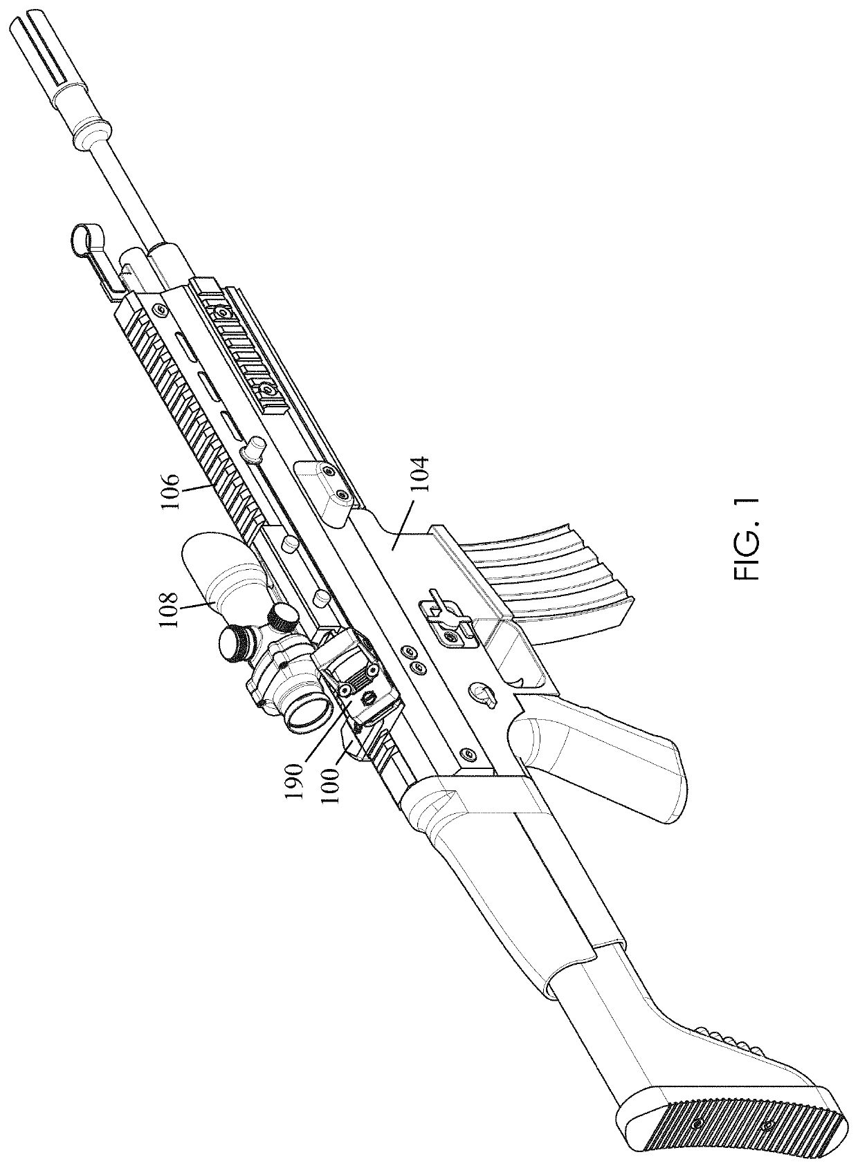
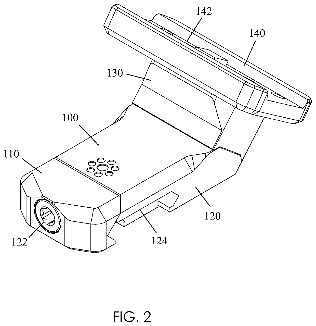
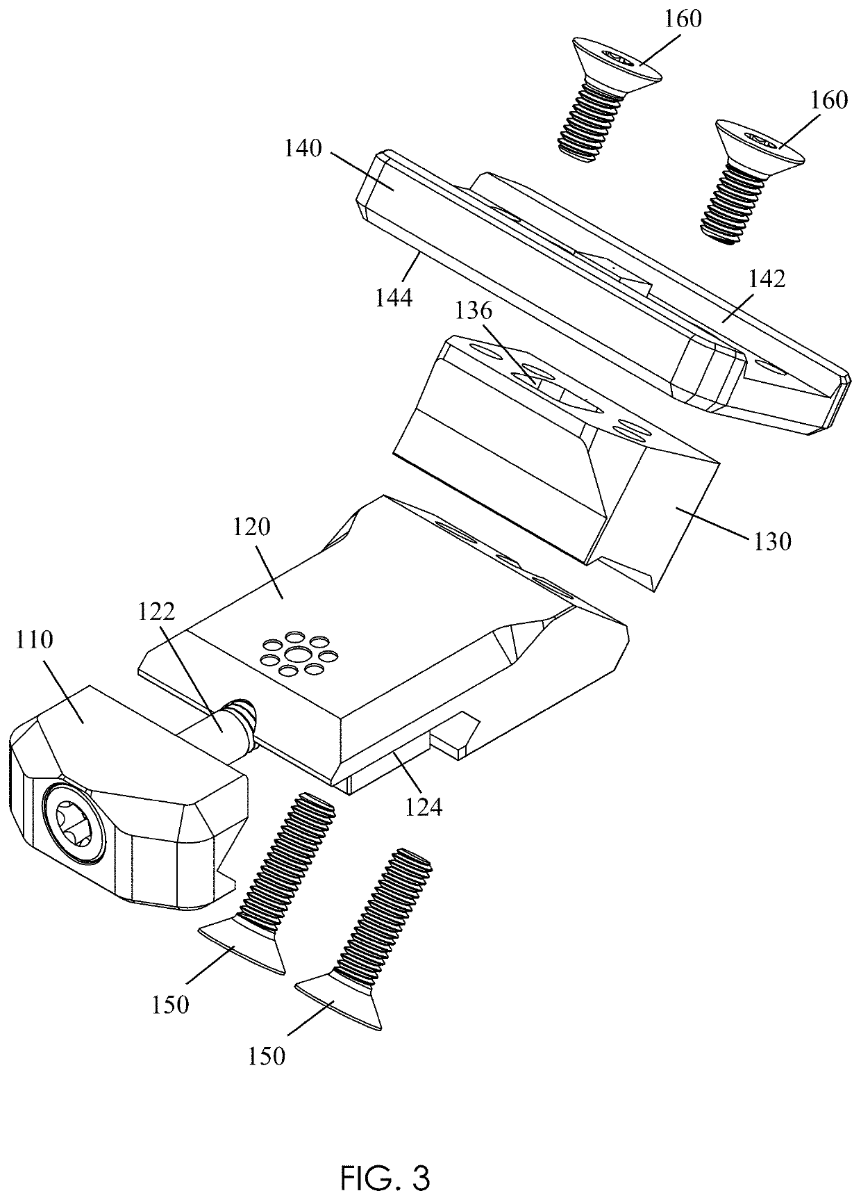
[0019]FIGS. 1-3 and 5-8 illustrate an example offset optic mount 100 according to the principles of the present disclosure. As shown in FIG. 1, the offset optic mount 100 can be mounted to an accessory rail 106 (e.g., a MIL-STD-1913 rail) extending along the top of a receiver or handguard of a modern sporting rifle 104 (e.g., an AR-15 / M4 style firearm) and is adapted to laterally offset an attached optical sight 190 from the accessory rail 106. The offset optic mount 100, and attached optical sight 190, can be used in conjunction with a telescopic sight 108 and can be mounted on the same accessory rail 106 as the telescopic sight 108. Further, the offset optic mount 100 can be configured by the user to offset the attached optical sight 190 at one of two different angles. In this way, for example, the offset optic mount 100 can be used to position the attached optical sight as close as is possible to the telescopic sight 108 without the view through the optical sight 190 being obstru...


PUM


Abstract

An offset optic mount can be detachably mounted at its proximal end to an accessory rail of a firearm in a cantilevered fashion with its distal end extending laterally from the firearm. An offset optic mount includes: a base and a clamp member on the proximal end, the base is adapted to be mounted to the accessory rail by the clamp member; an optic adapter plate on the distal end, the optic adapter plate is configured so that an optical sight can be attached thereto, the optic adapter plate is offset at an angle relative to the longitudinal axis of the base; and a stem adapted to connect the optic adapter plate to the base, the stem is a reversable piece used to set and change the offset angle of the optic adapter plate relative to the longitudinal axis of the base.

Description

CROSS REFERENCE TO RELATED APPLICATION[0001]This application claims the benefit of U.S. Provisional Application Ser. No. 62 / 889,694, which was filed on Aug. 21, 2019, the entirety of which is incorporated herein by reference.TECHNICAL FIELD[0002]This disclosure relates to implementations of an optic mount adapted to laterally offset an attached optical sight from the top of a firearm receiver or handguard.BACKGROUND[0003]Shooters often use rifles to engage targets at varying ranges. Often, shooters will use a particular sighting system based on the expected target engagement range. In general, telescopic sights (i.e., scopes) provide superior performance at longer ranges (beyond 200 yards), but non-magnified electronic sights (e.g., a reflex sight) can be more effective for close-range target engagements (inside 200 yards). Rifles equipped with a telescopic sight are often equipped with an alternate, or “back up”, sighting system for use in the event that the telescopic sight become...

Claims


Application Information

Patent Timeline
Patent Type & Authority Patents(United States)
IPC IPC(8): F41G11/00F41G1/387
CPCF41G1/387F41G11/003F41G11/004F41G1/16
Inventor ROBERSON, WILLIAM
Owner ARISAKA LLC
Why Eureka
Try Eureka