Spring-loaded kinematic adjustment screw

a kinematic adjustment screw and spring-loaded technology, applied in the field of precision screws, can solve the problems of deformation and/or abrading of contact surfaces, rotating against contact surfaces, and deformation of detent contact surfaces

Inactive Publication Date: 2010-05-27
KOZAK EUGENIUSZ
View PDF11 Cites 11 Cited by
  • Summary
  • Abstract
  • Description
  • Claims
  • Application Information

AI Technical Summary

Benefits of technology

[0012]In operation, the screw threads through a base plate of an optical mount and the spherical member engages a contact surface of a stage plate of the optical mount. As the screw is turned, the countervailing tensions of the spring and a compressive means of the optical mount holds the spherical member immobile, such that one or more (depending on the configuration of the contact surface) stable contact points are established between the proximal end of the screw and the contact surface of the stage plate. Since the spherical member does not rotate in relation to the contact surface, friction between the proximal end of the screw and the contact surface is virtually eliminated, as is the potential for deformation and / or abrasion of the contact surfaces which would cause inconsistent and non-reproducible positioning the stage plate.

Problems solved by technology

A major impediment to a stable and consistent contact between the ball of the adjustment screw and the stage plate detent is the potential for deformation of the detent contact surfaces under the stress of the ball-tip applied against the resistance of the springs.
While these designs do tend to reduce axial stress by minimizing the points of contact between the ball-tip of the adjustment screw and the detent surface of the stage plate, the ball-tip will still rotate within the contact detent as the screw turns, thus potentially deforming and / or abrading the contact surfaces over time.
Here again, however, the rotational torque of the adjustment screws is applied directly to the ball members, causing them to rotate against the contact surfaces.
There is the obvious expense associated with the use of sapphire material.

Method used


Image

  • Spring-loaded kinematic adjustment screw
  • Spring-loaded kinematic adjustment screw
  • Spring-loaded kinematic adjustment screw

Examples


Embodiment Construction

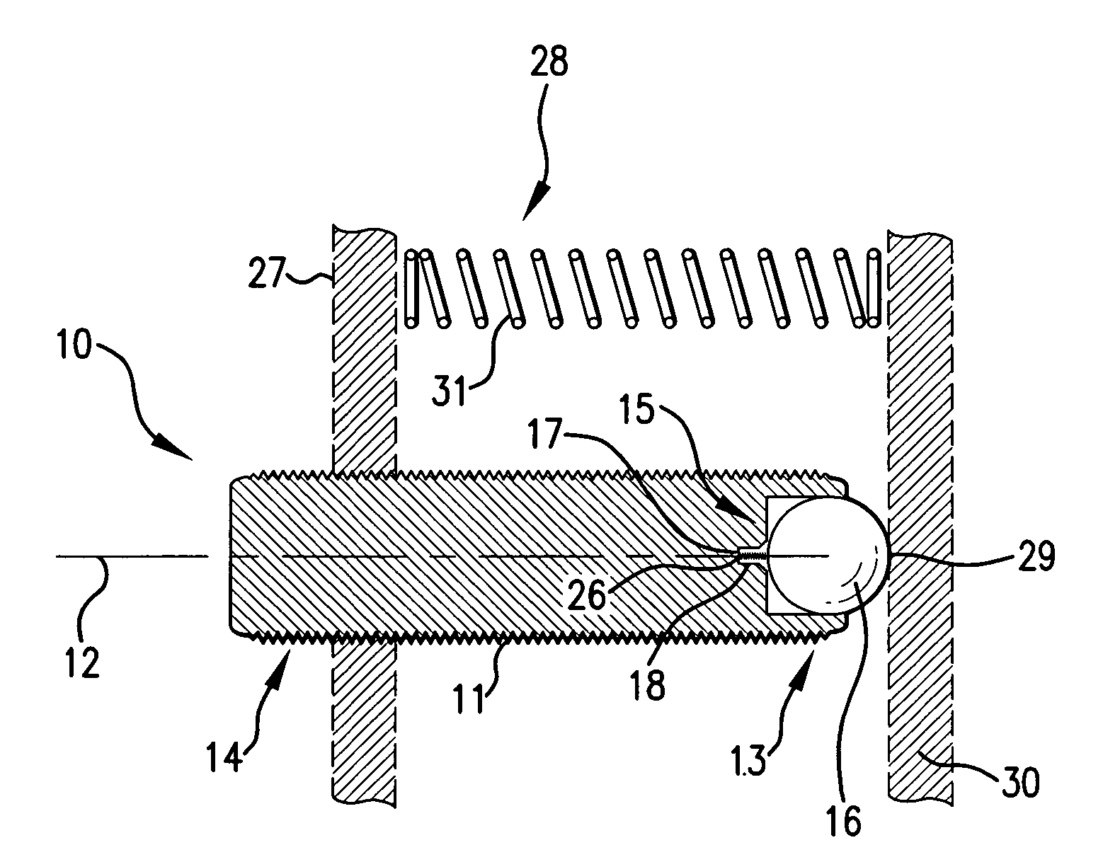
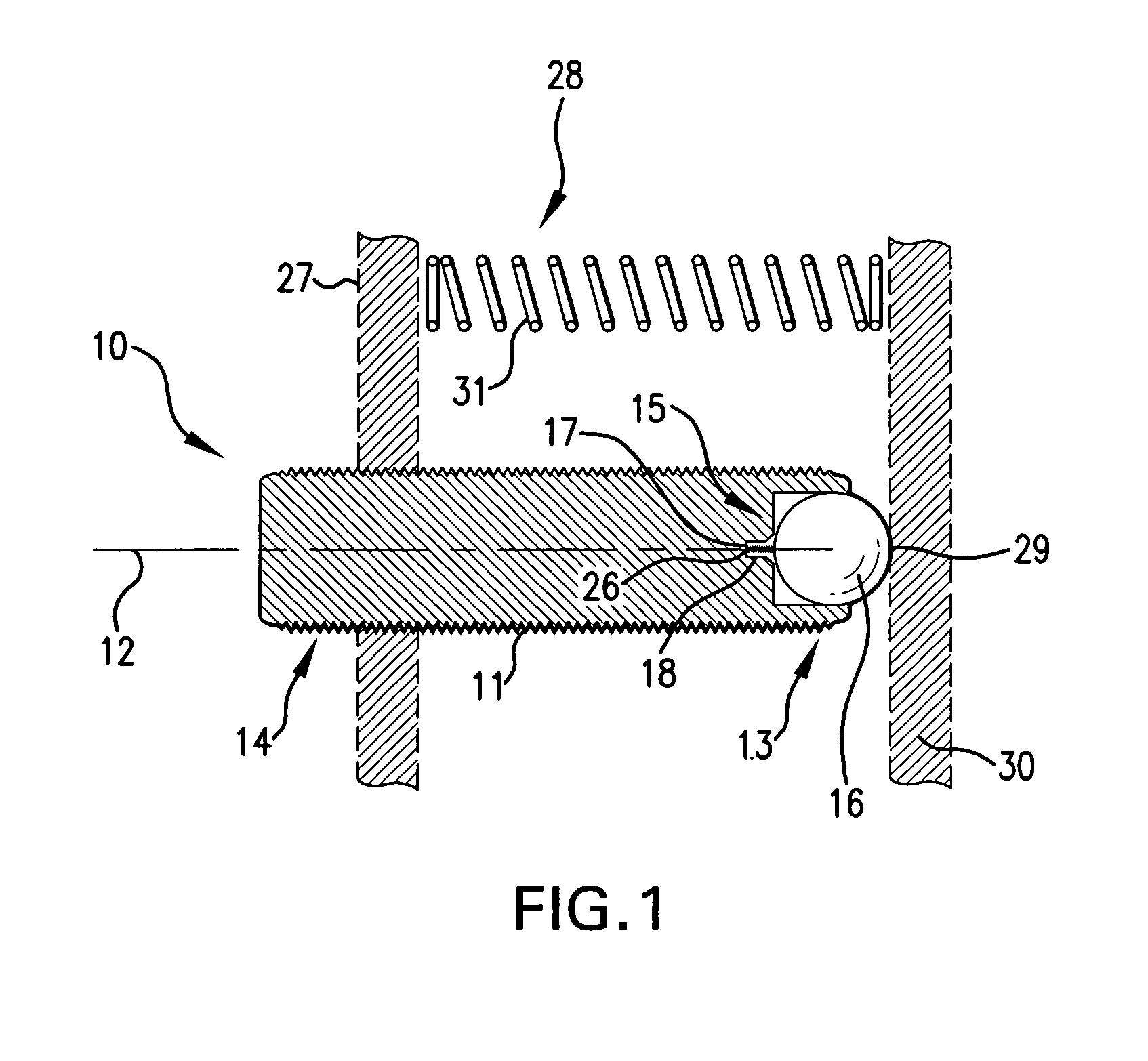
[0015]The present invention is a screw 10 comprising an externally threaded cylinder 11 having a medial axis 12, a proximal end 13 and a distal end 14. The distal end 14 can have a knob, a slot or other means (not shown) by which a torque can be applied to it in order to turn the screw 10. The proximal end 13 comprises a cavity 15, a spherical member 16, a spring 17, and a spring recess 18. The cavity 15 is a cylindrical cut-out in the proximal end 13 of the screw 10, and it comprises an open end 19, a closed end 20, and a radial wall 21.

[0016]The diameter of the cavity 15 is slightly larger than that of the spherical member 16, such that the spherical member 16 is free to rotate inside the cavity 15. At the open end 19 of the cavity 15 is a flange 22 that extends around the entire circumference of the cavity 15. The flange 22 forms a circular aperture having a diameter slightly less than that of the spherical member 16, such that the spherical member 16 is axially confined within t...


PUM


Abstract

A precision kinematic adjustment screw for optical mounts controls the position of the stage plate relative to the base plate so that the position is stable, consistent and reproducible. Use of a spring-loaded spherical member that is free to rotate independent of the screw minimizes friction between the proximal end of the screw and the contact surface of the stage plate and reduces the potential for deformation and/or abrasion of the contact surface.

Description

BACKGROUND OF THE INVENTION[0001]The present invention relates to precision screws used to make ultra-fine adjustments to the positions and / or angular orientations of optical components.[0002]Adjustable mounting apparatuses are commonly used in applications, such as interferometry and holography, in which precise positioning of optical components is essential. Such optical mounts typically comprise a pair of parallel plates: a base plate, which is rigidly fixed to a supporting base or surface, and a stage plate, on which optical components, such as mirrors, lenses, diffraction gratings, prisms, beam-splitters, light sources, and lasers, are mounted. Typically, the stage plate is coupled to the base plate by one or more compressive means—usually springs—which urge the two plates together. Countering the tensioning force of the springs are multiple kinematic adjustment members, which are typically ultra-fine pitch screws that control the position of the stage plate relative to the bas...

Claims


Application Information

Patent Timeline
Patent Type & Authority Applications(United States)
IPC IPC(8): A61B17/04
CPCG02B7/1825
Inventor KOZAK, EUGENIUSZ
Owner KOZAK EUGENIUSZ
Why Eureka
Try Eureka