
Zero cycle move using free list counts

a technology of free list counts and zero cycle moves, applied in the field of microprocessors, can solve the problems of limiting the maximum count for a given physical register identifier, the power consumption and latency of the capacitive word line and the corresponding word line buffer or driver, and the circuitry of the cam consumes an appreciable amount of power, so as to reduce the latency of data move operations

Active Publication Date: 2021-07-20
APPLE INC
View PDF44 Cites 1 Cited by
  • Summary
  • Abstract
  • Description
  • Claims
  • Application Information

AI Technical Summary

Benefits of technology

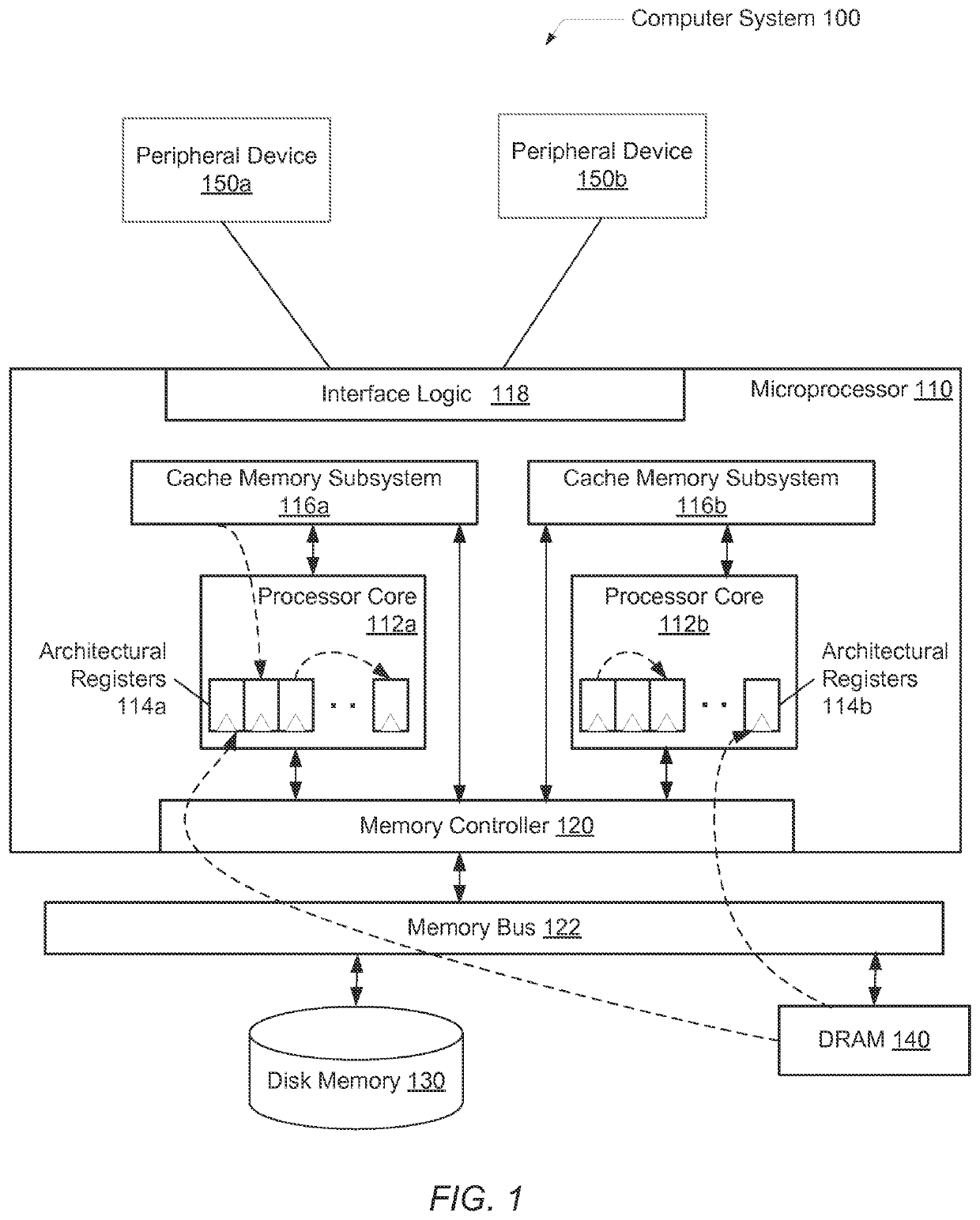
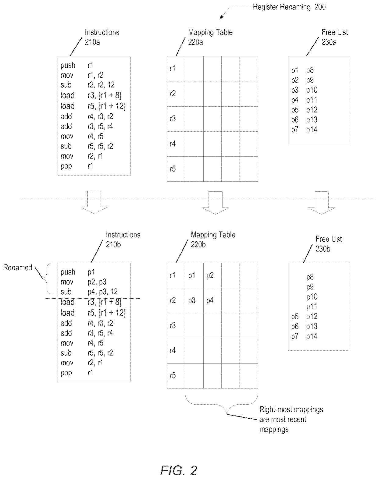
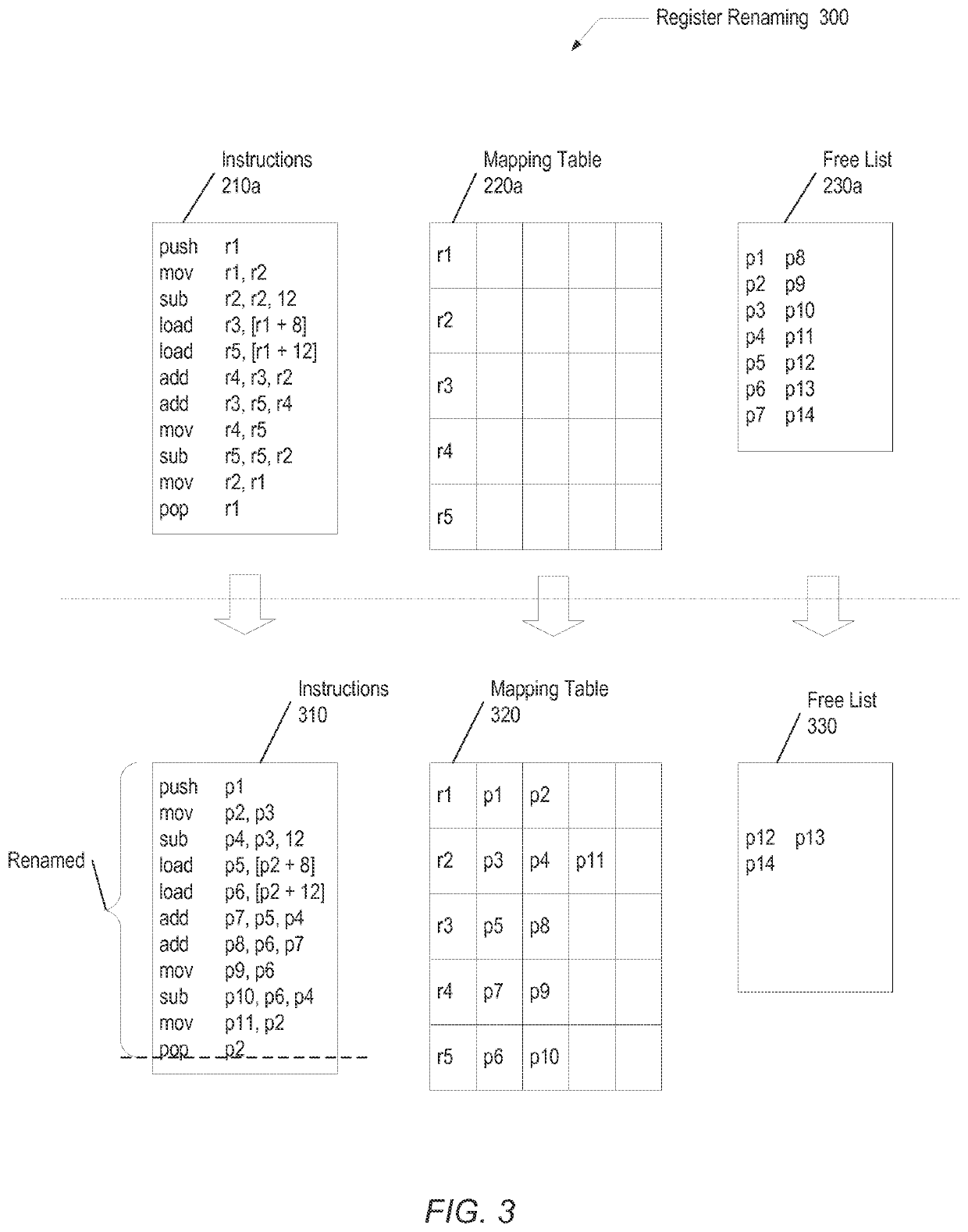
[0008]Systems and methods for efficiently reducing the latency of data move operations. In one embodiment, a processor includes a register rename unit configured to receive decoded instructions and determine whether a decoded given instruction qualifies to be a zero cycle move operation. Examples of qualifiers may be the move operation is a register-to-register move operation and support exists for maintaining a duplicate count of mappings for a given physical register number. If the determination is true, the rename register unit may assign a physical register number associated with a source operand of the given instruction to the destination operand of the given instruction. Each architectural register associated with the source operand and the destination operand may now be mapped to a same physical register number. In addition, control logic within the register rename unit may mark the given move instruction to prevent it from proceeding in the processor pipeline. For example, the control logic may mark the given move instruction to indicate completion at the dispatch pipeline stage.

Problems solved by technology

However, the circuitry for a CAM consumes an appreciable amount of power.
The power consumption and latency of the capacitive word lines and corresponding word line buffers or drivers limit both the number of entries in the CAM and the size of each entry.
Therefore, each of the number of physical register identifiers permitted to be duplicated at a given time and a maximum count for a given physical register identifier is limited.
When these limits are reached, the latency of subsequent move operations are no longer reduced and performance decreases.

Method used


Image

  • Zero cycle move using free list counts
  • Zero cycle move using free list counts
  • Zero cycle move using free list counts

Examples


Embodiment Construction

[0008]Systems and methods for efficiently reducing the latency of data move operations. In one embodiment, a processor includes a register rename unit configured to receive decoded instructions and determine whether a decoded given instruction qualifies to be a zero cycle move operation. Examples of qualifiers may be the move operation is a register-to-register move operation and support exists for maintaining a duplicate count of mappings for a given physical register number. If the determination is true, the rename register unit may assign a physical register number associated with a source operand of the given instruction to the destination operand of the given instruction. Each architectural register associated with the source operand and the destination operand may now be mapped to a same physical register number. In addition, control logic within the register rename unit may mark the given move instruction to prevent it from proceeding in the processor pipeline. For example, t...


PUM


Abstract

A system and method for reducing the latency of data move operations. A register rename unit within a processor determines whether a decoded move instruction qualifies for a zero cycle move operation. If so, control logic assigns a physical register identifier associated with a source operand of the move instruction to the destination operand of the move instruction. Additionally, the register rename unit marks the given move instruction to prevent it from proceeding in the processor pipeline. Further maintenance of the particular physical register identifier may be done by the register rename unit during commit of the given move instruction.

Description

BACKGROUNDTechnical Field[0001]Embodiments disclosed herein are related to microprocessors, and more particularly, to efficiently reducing the latency and power of data move operations.Description of the Relevant Art[0002]Microprocessors take advantage of instruction level parallelism (ILP) in source code with multiple techniques. One typical technique includes register renaming. Register renaming is used to allow parallel execution of instructions despite the occurrence of write after read (WAR) or write after write (WAW) data dependencies in a computer program. However, a true dependency, or a read after write (RAW) dependency, will remain. Therefore, architectural registers repeatedly used as a destination register and subsequently as a source register cause serialization of instruction execution for associated source code segments.[0003]One example of a common RAW dependency with an architectural register is assigning a base pointer a value stored in a stack pointer at the begin...

Claims


Application Information

Patent Timeline
Patent Type & Authority Patents(United States)
IPC IPC(8): G06F9/38G06F9/30
CPCG06F9/384G06F9/30032G06F9/30181
Inventor SUNDAR, SHYAM
Owner APPLE INC
Learn More