

Zero cycle move
a microprocessor and cycle move technology, applied in the field of microprocessors, can solve the problem of reducing the maximum throughput of the microprocessor to below n instructions, and achieve the effect of reducing the latency of data move operations
- Summary
- Abstract
- Description
- Claims
- Application Information
AI Technical Summary
Benefits of technology
Problems solved by technology
Method used
Image

Examples
Embodiment Construction
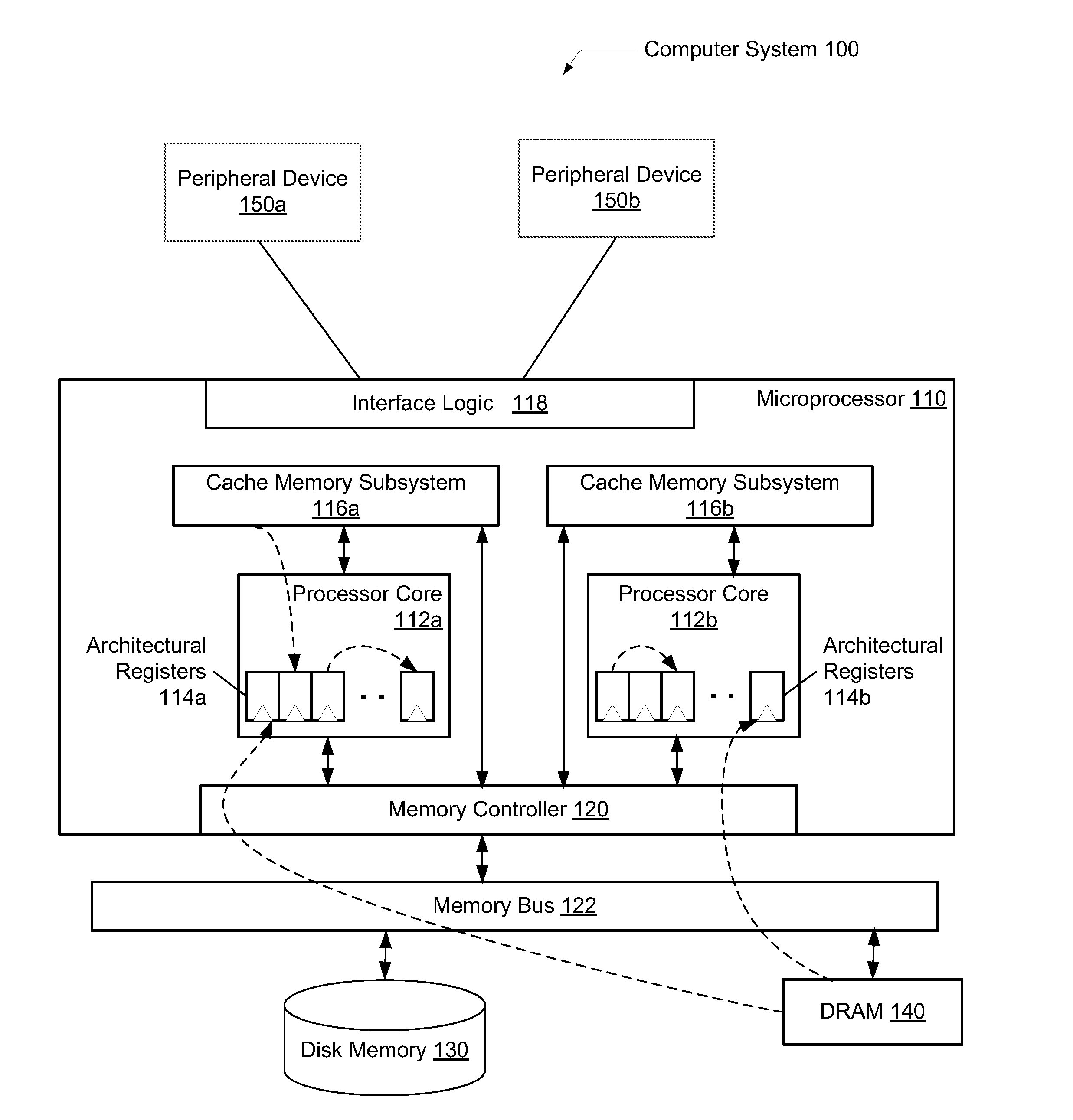
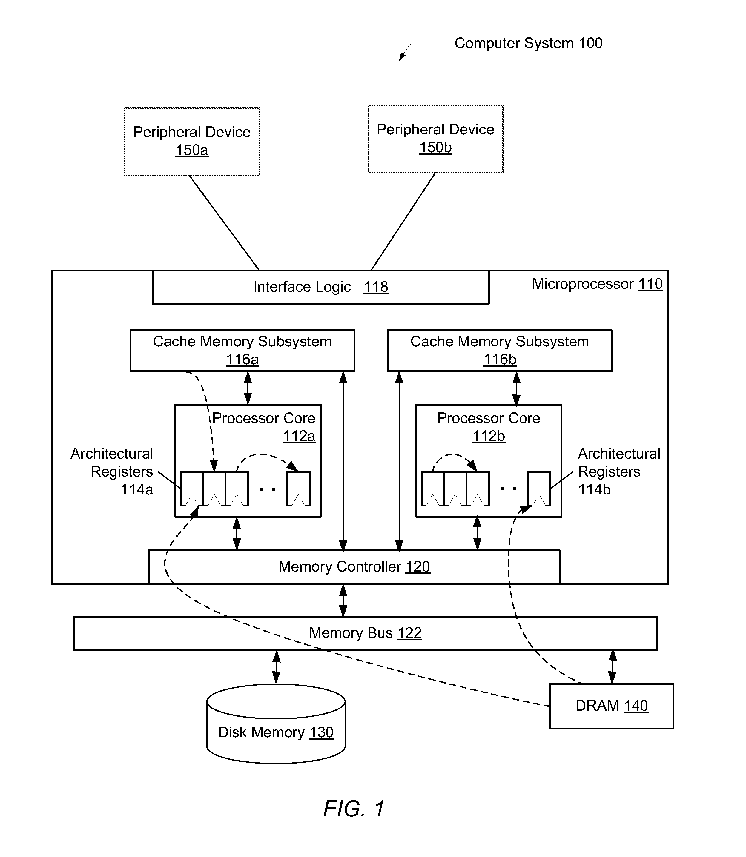
[0009]Systems and methods for efficiently reducing the latency of data move operations. In one embodiment, a processor includes a register rename unit configured to receive decoded instructions and determine whether a decoded given instruction qualifies to be a zero cycle move operation. Examples of qualifiers may be the move operation is a register-to-register move operation and support exists for maintaining a duplicate count of mappings for a given physical register number. If the determination is true, the rename register unit may assign a physical register number associated with a source operand of the given instruction to the destination operand of the given instruction. Each architectural register associated with the source operand and the destination operand may now be mapped to a same physical register number. In addition, control logic within the register rename unit may mark the given move instruction to prevent it from proceeding in the processor pipeline. For example, t...
PUM
 Abstract
Description
Claims
Application Information