Packet latency based arbitration technique for a packet switch

a packet switch and latency technology, applied in the field of packet-based communication systems, can solve the problems of increasing data packet throughput and reducing routing congestion, and achieve the effect of promoting fair routing of data packets

Active Publication Date: 2011-09-06
INTEGRATED DEVICE TECH INC
View PDF42 Cites 17 Cited by
  • Summary
  • Abstract
  • Description
  • Claims
  • Application Information

AI Technical Summary

Benefits of technology

In various embodiments, a packet switch includes input ports having various input bandwidths. The packet switch initializes a credit value for each of the input ports and includes an arbiter for selecting input ports of the packet switch based on the credit values. Additionally, the packet switch includes a switch fabric that routes data units of data packets received from the selected input ports of the packet switch to output ports of the packet switch. The arbiter modifies the credit value of each selected input port based on the latency for routing a data packet from the selected input port to the switch fabric. The arbiter then selects input ports based on the modified credit values for routing additional data packets through the packet switch. In this way, the arbiter promotes fairness in routing data packets through the packet switch. Additionally, the packet switch replenishes the credit values upon the occurrence of one or more conditions in the packet switch, for example when a credit value reaches a replenishment threshold value.
Because the arbiter promotes fairness in routing data packets through the packet switch based on latencies of data packets routed through the packet switch, variance among the latencies of the data packets is reduced in the packet switch. As a result, performance of the packet switch increases. Additionally, routing congestion decreases and data packet throughput increases in the packet switch.

Problems solved by technology

Additionally, routing congestion decreases and data packet throughput increases in the packet switch.

Method used


Image

  • Packet latency based arbitration technique for a packet switch
  • Packet latency based arbitration technique for a packet switch
  • Packet latency based arbitration technique for a packet switch

Examples


Embodiment Construction

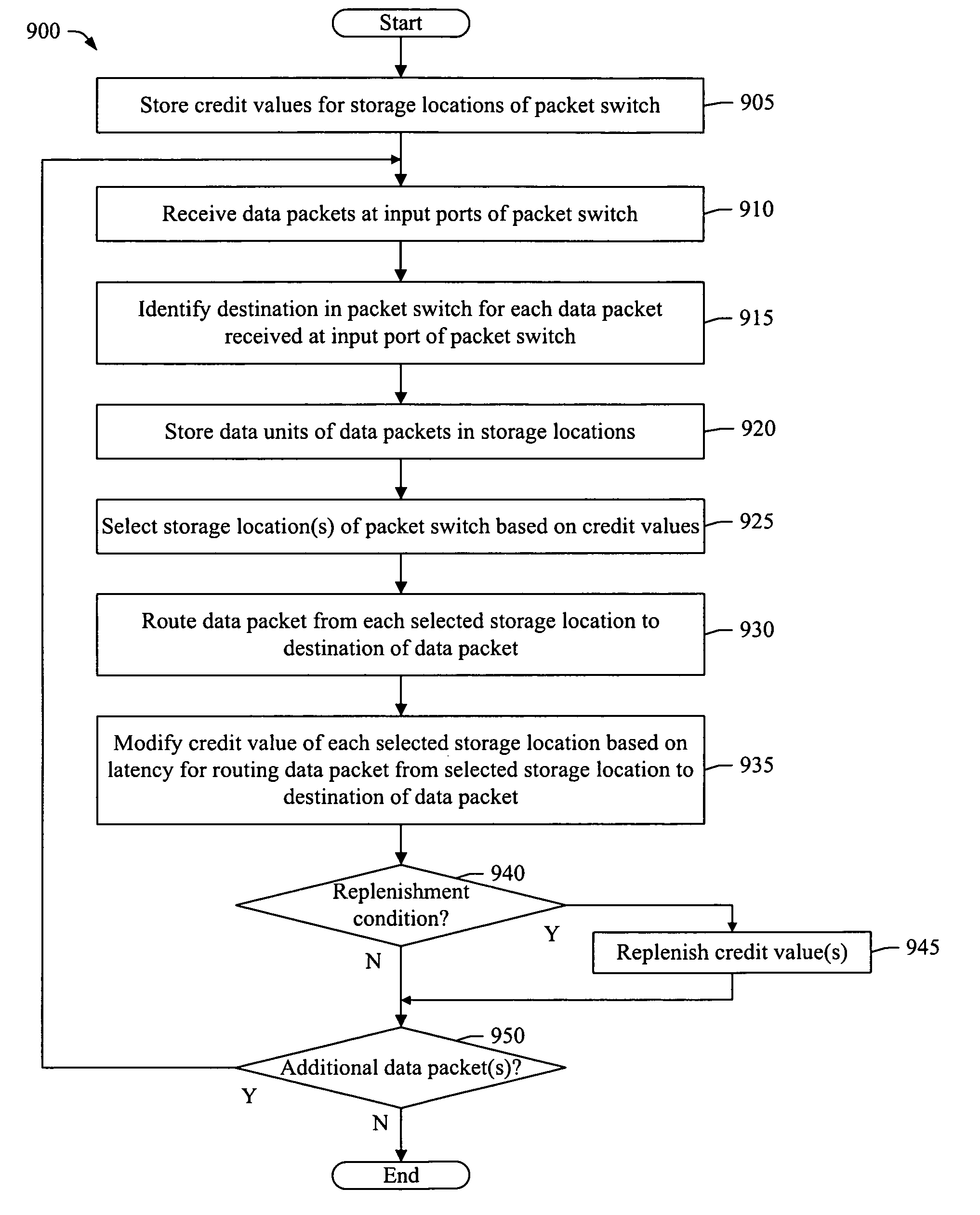
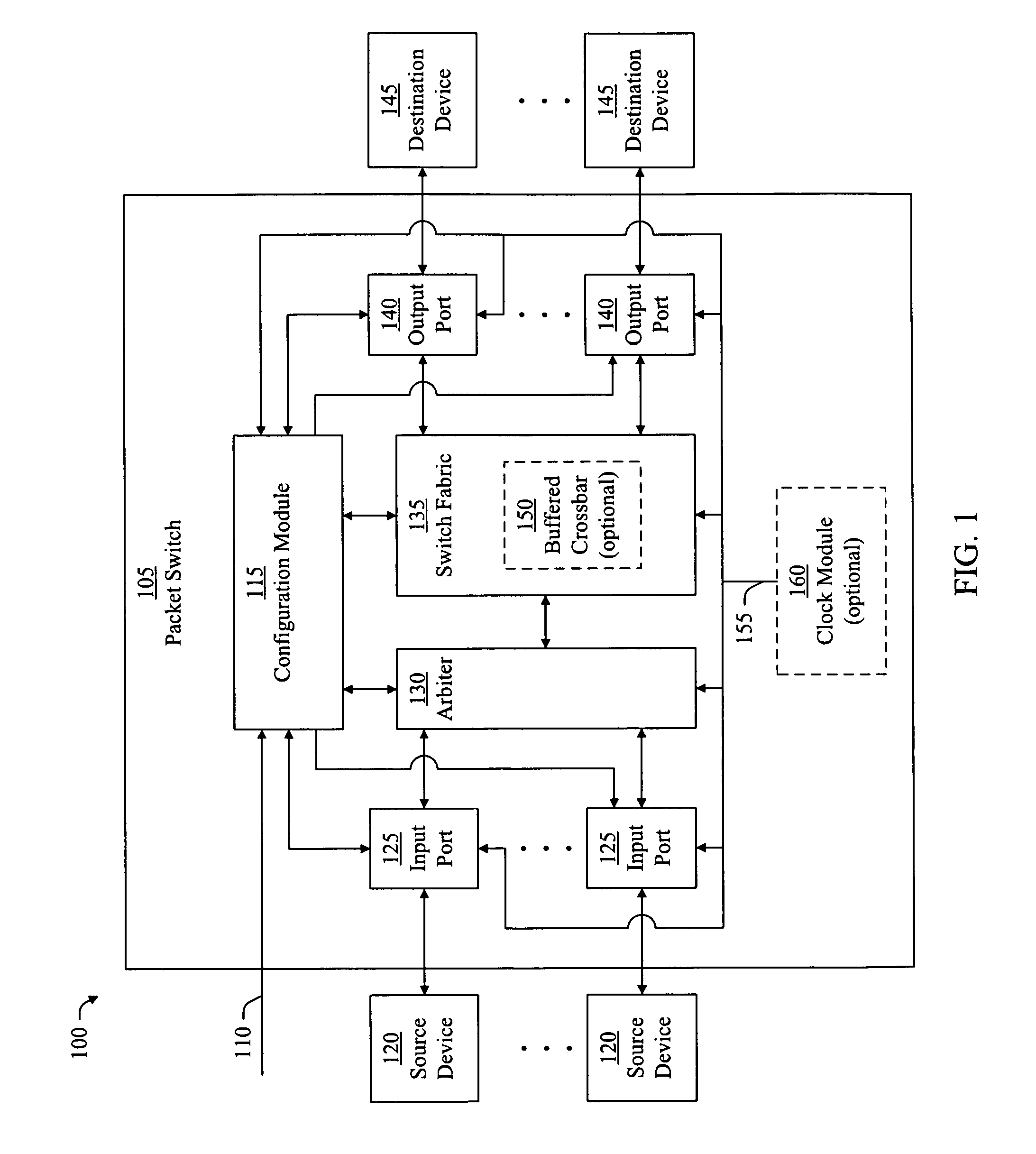
In various embodiments, a packet switch includes input ports having various input bandwidths for receiving data packets. The packet switch initializes credit values for the input ports and identifies destination output ports of the packet switch for data packets received by the input ports. An arbiter of the packet switch selects input ports for routing data packets through the packet switch based on the credit values. A switch fabric of the packet switch routes data packets from the select input ports to the destination output ports of the data packets. Moreover, the arbiter modifies the credit value of each selected input port based on the latency for routing a data packet from the selected input port to the switch fabric. The arbiter then selects input ports based on the modified credit values for routing additional data packets through the packet switch. In this way, the arbiter promotes fairness in routing data packets through the packet switch. The packet switch replenishes th...


PUM


Abstract

A packet switch including input ports having various input bandwidths initializes credit values for the input ports. An arbiter of the packet switch selects input ports based on the credit values and routes data packets from the selected input ports to a switch fabric of the packet switch. The switch fabric routes data packets from the selected input ports to output ports of the packet switch. Moreover, the arbiter modifies the credit value of each selected input port based on the latency for routing the data packet from the selected input port to the switch fabric. In this way, the arbiter promotes fairness in routing additional data packets through the packet switch. In some embodiments, the switch fabric includes a buffered crossbar and the arbiter modifies credit values of crosspoints in the buffered crossbar based on the latency for routing data packets from the crosspoints to the output ports.

Description

BACKGROUNDA packet-based communication system includes packet switches for routing data packets through a communication network. Each packet switch in the communication network receives data packets at input ports of the packet switch and routes the data packets to output ports of the packet switch. In this way, the data packets are transmitted through the communication network. In some instances, a packet switch in the communication network receives data packets at more than one input port of the packet switch that are to be routed to the same output port of the packet switch. In these instances, an arbiter in the packet switch selects one of the input ports and routes the data packet from the selected input port to the output port. The arbiter repeats this process for the remaining input ports until each of the data packets is routed from a selected input port to the output port.In one type of arbitration technique employed in a packet switch, the arbiter promotes fairness in sele...

Claims


Application Information

Patent Timeline
Patent Type & Authority Patents(United States)
IPC IPC(8): H04L12/417H04L12/20H04L12/26
CPCH04L47/10H04L49/15H04L49/253H04L49/65
Inventor MACADAM, ANGUS DAVID STARR
Owner INTEGRATED DEVICE TECH INC
Why Eureka
Try Eureka