Launching device for launching an object

Active Publication Date: 2021-07-27
SKYCAT OY
View PDF15 Cites 0 Cited by
  • Summary
  • Abstract
  • Description
  • Claims
  • Application Information

AI Technical Summary

Benefits of technology

[0010]In view of prior art most advantageous for the invention may be that a force for maintaining a casing around a launchable object effecting to a lever via the casing is substantially smaller than a force stressing the casing at the location, where it prevents a push element from turning due to a spring force. When force is supplied from a part of the casing, which connects said frame and the push element, to the lock element and lever of it, friction forces eliminate most of the force on the way. While the casing is flattened against the launchable object and the frame, as well as corners of the frame, due to inventive structure such high friction forces effecting on the casing are generated that the force effecting to the lock device via the casing is substantially smaller compared to a force for keeping the frame and the push element together.
[0011]The previously presented is followed by an immediate advantage of enabling realizing a lock element, such as e.g. a servo equipped with decreased power and charging capacity of energy supplying accumulator / battery, as well as physical weight.

Problems solved by technology

A challenge to such is posed by enablement of securing such strict enough locking and at the same time assuring release of the locking when necessary.
The biggest disadvantage of the known launching device may be considered to be an issue that a force for maintaining a casing around a launchable object effecting to a lever via the casing is substantially equal with a force stressing the casing for preventing turning of push element.
Due to the previously mentioned disadvantage power of an apparatus for maintaining locking of casing, such as a servo, needs to be fitted in accordance to the force.

Method used


Image

  • Launching device for launching an object
  • Launching device for launching an object

Examples


Embodiment Construction

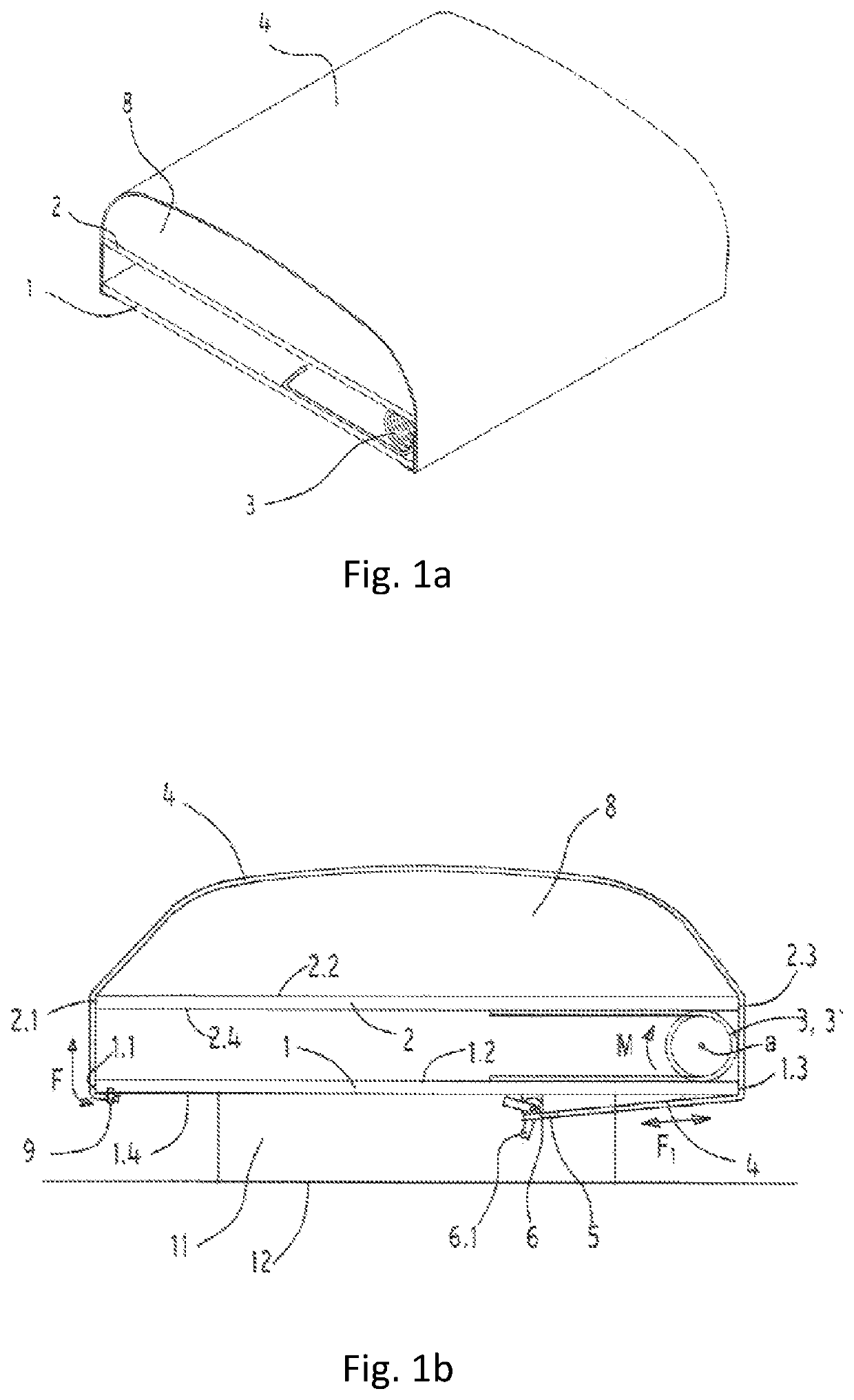
[0018]In the following a structure and an operation of an advantageous implementation of the invention is described with reference to the accompanying figures.

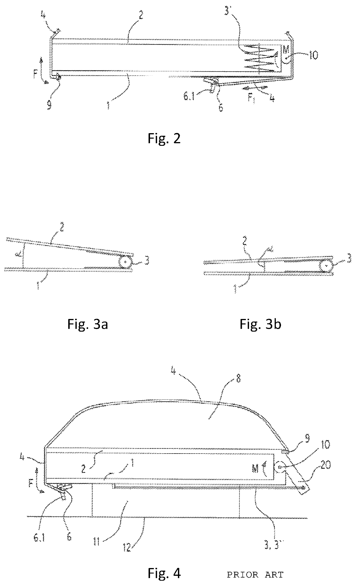
[0019]FIG. 4 illustrates an arrangement, which is a base for known technology. A frame 1 of a launching device and a push element 2 have been superposed onto each other and those have been fixed to each other at one side of the arrangement such that at a certain moment of launch, push element is capable of turning in relation to the frame around a swivel 10, which is functioning as a pivot point. A (launchable) object 8 is arranged against the push element 2 and the object 8 has been enveloped by a casing 4, which is fixed at one end to the push element, at a fixing point 9 next to the swivel and at the other end to a lock element 6 fixed to the frame 1, at the other edge of the arrangement. The casing 4, being locked to the lock element 6, keeps the push element 2 in place and prevents excited elastic bands 3″ (two elastic ba...


PUM


Abstract

A device for launching an object is described. The device comprises a frame affixed to the launch pad, a push element for pushing an object detached from the launch pad, and a flexible force storing element for turning the push element in relation to the frame. The device has a casing fixed to the frame at a fixing point for holding the object in place against the push element. The device has a lock element for locking the casing in standby position. The frame and the push element are superposed and connected to each other at one edge of the device. The frame and the push element are substantially parallel. Force stored in the force storing element is releasable for displacing the push element at a moment of launch. The force storing element may be at least one spring or elastic band or an extension spring.

Description

PRIORITY[0001]This application is U.S. National Phase application of PCT application number PCT / FI2017 / 050161 filed on Mar. 13, 2017 and claiming priority of Finnish national application number FI20160062 filed on Mar. 14, 2016, the contents of both of which are incorporated herein by reference.FIELD AND BACKGROUND[0002]An object of the invention is a launching device for launching an object from a launch pad, wherein said apparatus comprises a frame affixed to the launch pad, a push element for pushing an object detached from the launch pad, a flexible force storing element for turning the push element in relation to the frame, a casing for holding the launchable object in place against the push element, and a lock element for locking the casing in standby position and for bringing the launching device in a position of ready to operate such that the frame and the push element are superposed and connected to each other substantially at one edge of the device, the frame and the push ...

Claims


Application Information

Patent Timeline
Patent Type & Authority Patents(United States)
IPC IPC(8): B64D17/70B64D17/80
CPCB64D17/70B64D17/80B64C2201/185B64F1/04B64D1/06B64D1/12B64U70/83
Inventor HIISILÄ, HENRI
Owner SKYCAT OY
Why Eureka
Try Eureka