
Vehicle accelerator pedal having dual hysteresis generating structure

a technology of generating structure and accelerator pedal, which is applied in the direction of mechanical control devices, instruments, propulsion unit arrangements, etc., can solve the problems of complex structure, high cost, and high cost, and achieves the effect of reducing the fatigue of the driver's ankle, and easily changing the magnitude of hysteresis

Active Publication Date: 2021-08-03
KYUNG CHANG IND
View PDF8 Cites 1 Cited by
  • Summary
  • Abstract
  • Description
  • Claims
  • Application Information

AI Technical Summary

Benefits of technology

This design reduces driver fatigue by generating hysteresis with a simple configuration, preventing return defects and dispersing concentrated loads, thus minimizing abrasion and improving pedal return functionality.

Problems solved by technology

The mechanical accelerator pedal has an operational problem due to an ambient environment, a change in temperature, a degradation of the cable, and the like.
In addition, hysteresis needs to be generated to reduce the driver's fatigue caused by the operation of the electronic accelerator pedal.
The hysteresis generating technologies, which are applied to the electronic accelerator pedals in the related art, include a structural friction method, a housing friction method, and the like, but have problems of having complicated structures and requiring many components.
Even in a case in which the accelerator pedal has a hysteresis generating structure, a load is concentrated on a particular site having a narrow area and causes abrasion.
As a result, there is a problem such as a return defect in which the pedal does not return to its original position after the pedal is released.

Method used


Image

  • Vehicle accelerator pedal having dual hysteresis generating structure
  • Vehicle accelerator pedal having dual hysteresis generating structure
  • Vehicle accelerator pedal having dual hysteresis generating structure

Examples


Embodiment Construction

[0040]The following detailed description of the present invention will be made with reference to the accompanying drawings illustrating specific exemplary embodiments for carrying out the present invention. These exemplary embodiments will be described in detail enough to carry out the present invention by those skilled in the art. It should be understood that various exemplary embodiments of the present invention are different from one another but need not be mutually exclusive. For example, particular shapes, structures, and characteristics described herein in respect to one exemplary embodiment may be implemented in other exemplary embodiments without departing from the spirit and scope of the present invention. In addition, it should be understood that the position or arrangement of each constituent element in the respective disclosed exemplary embodiments may be changed without departing from the spirit and scope of the present invention. Therefore, the following detailed descr...


PUM


Abstract

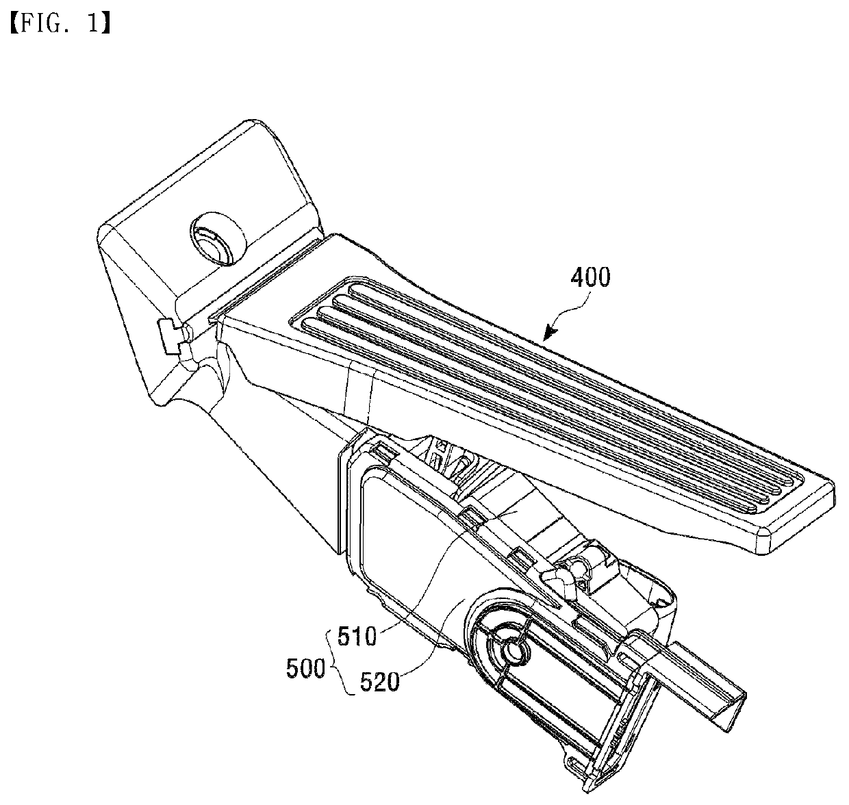
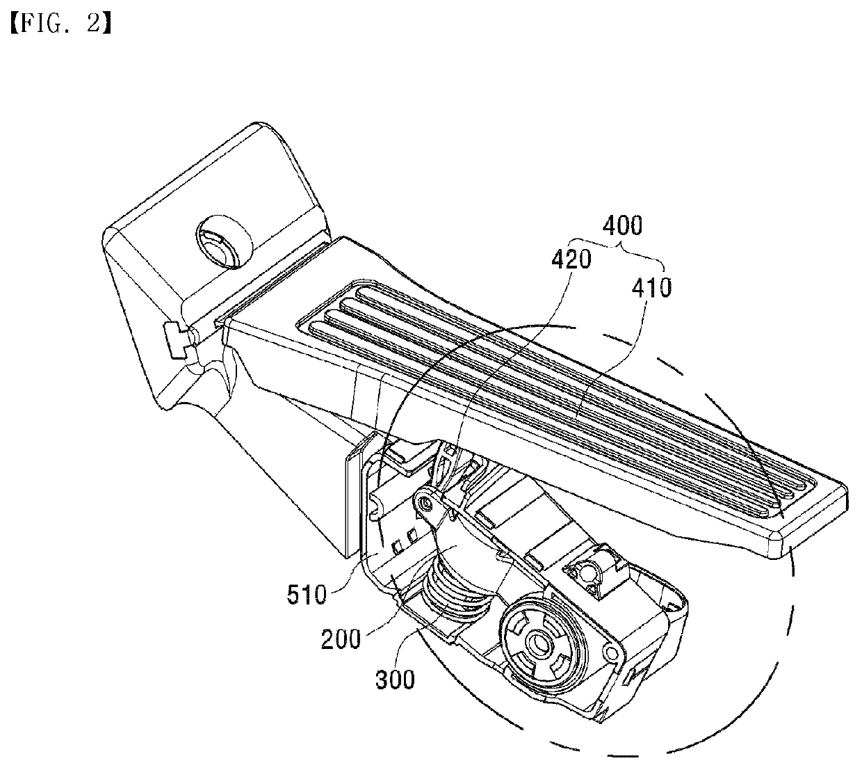
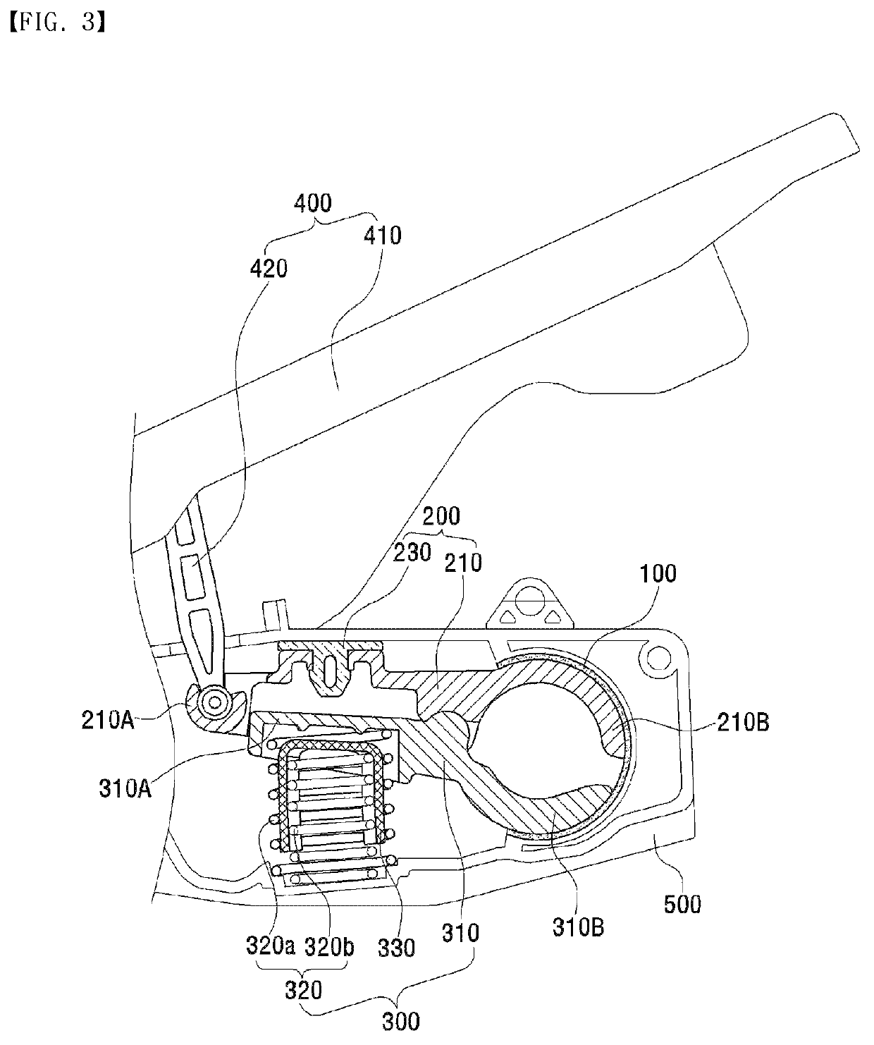
Disclosed is a vehicle accelerator pedal that may include a cylindrical hinge unit, a lever unit having one side configured to operate in a first direction and another side formed to correspond to an inner circumferential edge of the hinge unit and configured to operate in a second direction opposite the first direction. An outer circumferential edge may be configured to come into close contact with an upper inner circumferential edge of the hinge unit such that a moment of force is applied in a first rotation direction by the hinge unit. An elastic unit having one side may be configured to elastically support one side of the lever unit, the other side formed to correspond to the inner circumferential edge of the hinge unit. An outer circumferential edge may be configured to come into close contact with a lower inner circumferential edge of the hinge unit.

Description

CROSS-REFERENCE TO RELATED APPLICATIONS[0001]This application claims priority to and the benefit of Korean Patent Application No. 10-2019-0014830 filed in the Korean Intellectual Property Office on Feb. 8, 2019, the entire contents of which are incorporated herein by reference.TECHNICAL FIELD[0002]The present invention relates to a vehicle accelerator pedal, and more particularly, to a vehicle accelerator pedal having a dual hysteresis generating structure.BACKGROUND ART[0003]An accelerator pedal is used to accelerate an operation of an engine. A driver pushes the accelerator pedal to increase a rotational speed of the engine and accelerate a vehicle, and the driver releases the accelerator pedal to decrease the rotational speed. The accelerator pedal is connected to a throttle valve through a wire and a linkage. When the accelerator pedal is pushed, the throttle valve is opened, air is drawn into cylinders, and an electronically controlled fuel injection device detects the amount o...

Claims


Application Information

Patent Timeline
Patent Type & Authority Patents(United States)
IPC IPC(8): B60K26/02G05G1/44G05G5/05
CPCB60K26/02G05G1/44G05G5/05G05G2505/00G05G1/445G05G5/03B60K26/021G05G1/30
Inventor KIM, HYEON UKKIM, BEOM JUN
Owner KYUNG CHANG IND
Learn More