Portable rowing frame

a frame and frame technology, applied in the field of rowing exercise machines, can solve the problems of difficult for active users to move around and the machine is not meant to move to other positions, and achieve the effect of convenient handling of the rowing machin

Active Publication Date: 2021-08-10
ARLU LLC
View PDF25 Cites 7 Cited by
  • Summary
  • Abstract
  • Description
  • Claims
  • Application Information

AI Technical Summary

Benefits of technology

[0005]The present invention is a rowing frame. The rowing frame comprises a front rowing beam, a rear rowing beam, a mounting beam, a rowing seat, at least one leg, and a pedal assembly. The front rowing beam and the rear rowing beam each comprises a slider rail and a mounting channel. The front rowing beam comprises a first mounting element. The slider rail traverses from the front rowing beam to the rear rowing beam. The mounting channel traverses from the front rowing beam to the rear rowing beam, opposite to the slider rail. The rear rowing beam is removably attached to the front rowing beam through a connection element. The first mounting element is positioned opposite to the rear rowing beam along the front rowing beam. The mounting beam is removably attached to the first mounting element, where the mounting beam is configured to mount a portable resistance device that facilitates a rowing machine handle. The rowing seat is slidably attached to the slider rail. At least one leg is distributed about the mounting channel. The pedal assembly is connected adjacent to the front rowing beam, opposite to the rear rowing beam.

Problems solved by technology

Exercise machines are often bulky and heavy pieces of equipment that can make it difficult for active users to easily move around.
However, such a machine is not meant for moving to other positions or for travel.
Many of these machines are also only capable of a single type of exercise, specifically a rowing motion which can leave a user wanting for a more diverse workout session.

Method used


Image

  • Portable rowing frame
  • Portable rowing frame
  • Portable rowing frame

Examples


Embodiment Construction

[0012]All illustrations of the drawings are for the purpose of describing selected versions of the present invention and are not intended to limit the scope of the present invention. The present invention is to be described in detail and is provided in a manner that establishes a thorough understanding of the present invention. There may be aspects of the present invention that may be practiced or utilized without the implementation of some features as they are described. It should be understood that some details have not been described in detail in order to not unnecessarily obscure focus of the invention. References herein to “the preferred embodiment”, “one embodiment”, “some embodiments”, or “alternative embodiments” should be considered to be illustrating aspects of the present invention that may potentially vary in some instances, and should not be considered to be limiting to the scope of the present invention as a whole.

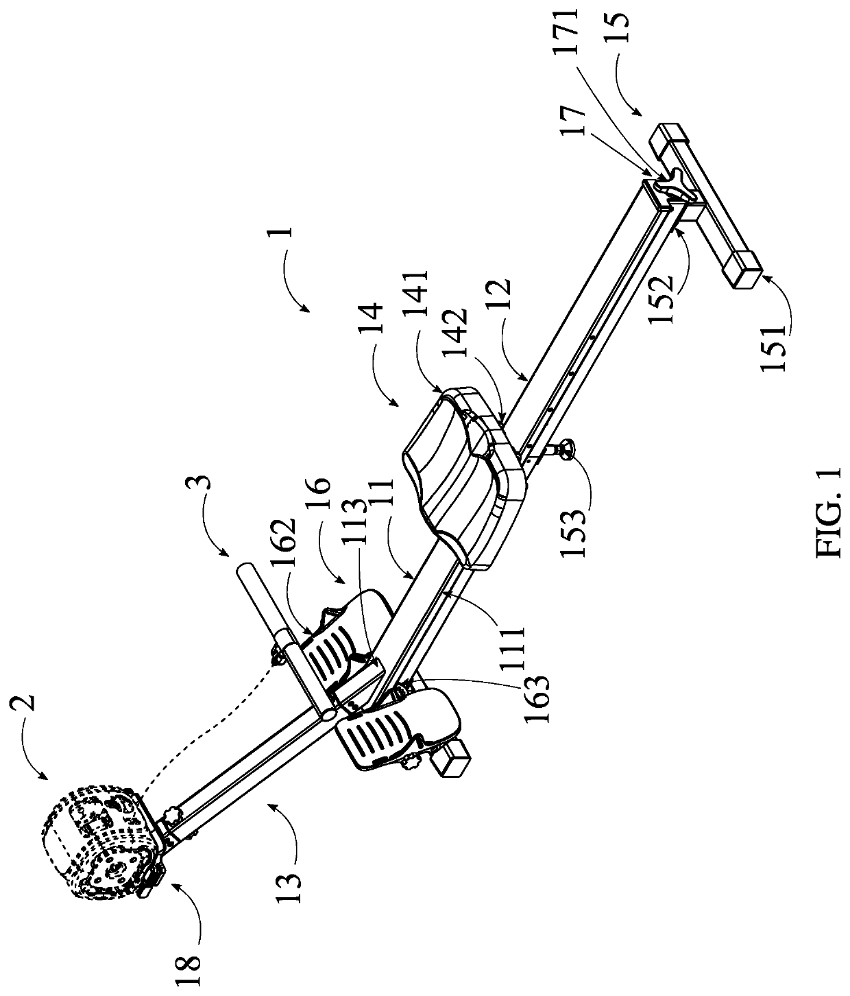
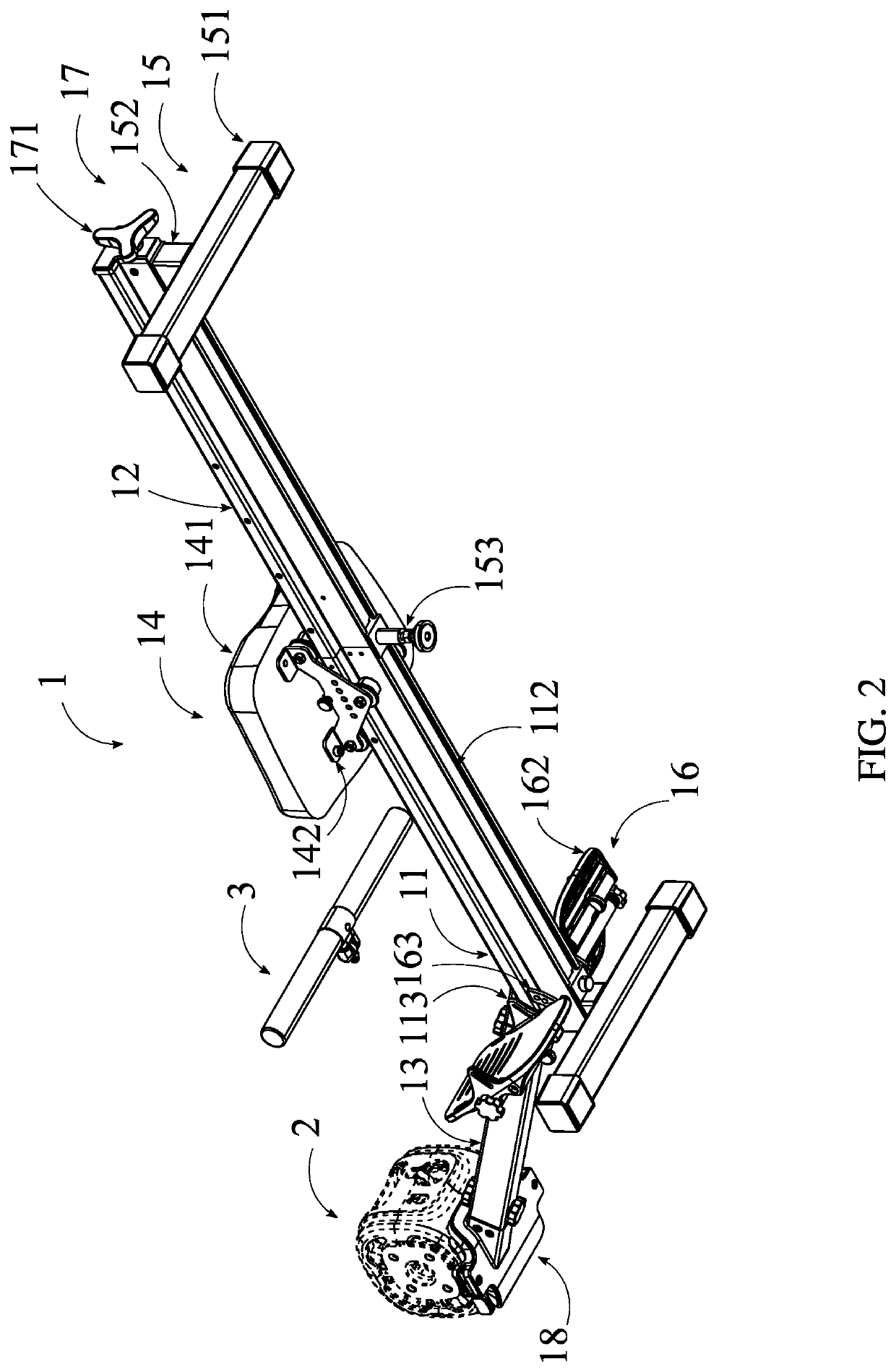
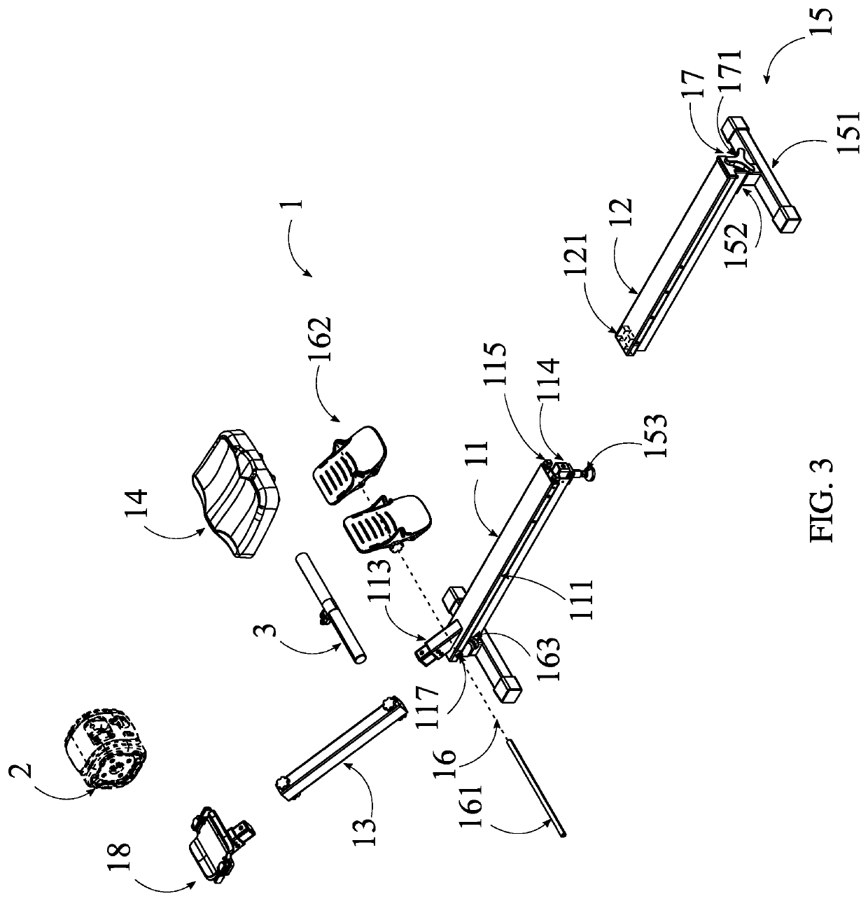
[0013]In reference to FIGS. 1-5, the present invention ...


PUM


Abstract

A portable rowing frame that mounts a portable resistance device is presented. The rowing frame contains a front rowing beam, a rear rowing beam, a mounting beam, a rowing seat, at least one leg, and a pedal assembly. The front rowing beam and the rear rowing beam each contains a slider rail and a mounting channel. The front rowing beam contains a first mounting element. The slider rail and the mounting channel traverses from the front rowing beam to the rear rowing beam. The rear rowing beam is attached to the front rowing beam through a connection element. The first mounting element is positioned to the front rowing beam. The mounting beam is attached to the first mounting element. The rowing seat is attached to the slider rail. The legs are distributed about the mounting channel. The pedal assembly is connected to the front rowing beam.

Description

[0001]The current application is a continuation-in-part (CIP) application of a U.S. non-provisional application Ser. No. 17 / 086,122 filed on Oct. 30, 2020. The U.S. non-provisional application Ser. No. 17 / 086,122 claims a priority to a U.S. provisional application Ser. No. 63 / 045,553 filed on Jun. 29, 2020.FIELD OF THE INVENTION[0002]The present invention relates generally to a rowing exercise machines. More specifically, the present invention is a portable rowing frame configured to mount a portable resistance device such that it functions as a rowing exercise machine.BACKGROUND OF THE INVENTION[0003]Exercise machines are often bulky and heavy pieces of equipment that can make it difficult for active users to easily move around. More particularly, indoor rowing machines have a large frame in which a user can sit in to more comfortably perform exercises and to simulate the position assumed when rowing a physical boat. However, such a machine is not meant for moving to other position...

Claims


Application Information

Patent Timeline
Patent Type & Authority Patents(United States)
IPC IPC(8): A63B22/00A63B21/00
CPCA63B22/0076A63B21/4034A63B22/0087A63B2022/0079A63B23/03533
Inventor TIPPLE, LUKECOUSINEAU, TIZIANORILEY, DAVID
Owner ARLU LLC
Why Eureka
Try Eureka